TCP/IP: DHCP and Autoconfiguration
To make use of the TCP/IP protocol suite, each host and router requires a certain amount of configuration information.
-
Every interface to be used with TCP/IP networking requires an
-
IP address,
-
subnet mask, and
-
broadcast address (for IPv4).
-
-
To engage in communication beyond the local subnet, called indirect delivery, a system requires a routing or forwarding table that indicates what router(s) are to be used for reaching various destinations.
-
To be able to use services such as the Web and e-mail, the DNS is used to map user-friendly domain names to the IP addresses required by the lower-protocol layers.
-
To use Mobile IP, a system also needs to know how to find a home agent.
All in all, having an IP address, subnet mask, and the IP address of a DNS server and router are the bare essentials to get a system running on the Internet that is capable of using or providing popular services such as Web and e-mail.
Beyond the bare essentials, there are numerous other bits of configuration information a host or router may require, depending on the types of services it uses or provides.
-
These may include the locations of home agents, multicast routers, VPN gateways, and Session Initiation Protocol (SIP)/VoIP gateways.
- 1. Dynamic Host Configuration Protocol (DHCP)
- 2. Stateless Address Autoconfiguration (SLAAC)
- 3. PPP over Ethernet (PPPoE)
- References
1. Dynamic Host Configuration Protocol (DHCP)
DHCP [RFC2131] is a popular client/server protocol used to assign configuration information to hosts (and, less frequently, to routers).
DHCP is very widely used, in both enterprises and home networks.
-
Even the most basic home router devices support embedded DHCP servers.
-
DHCP clients are incorporated into all common client operating systems and a large number of embedded devices such as network printers and VoIP phones.
Such devices usually use DHCP to acquire their IP address, subnet mask, router IP address, and DNS server IP address.
-
Information pertaining to other services (e.g., SIP servers used with VoIP) may also be conveyed using DHCP.
-
DHCP was originally conceived for use with IPv4, IPv6 can also use a version of DHCP called DHCPv6 [RFC3315].
The design of DHCP is based on an earlier protocol called the Internet Bootstrap Protocol (BOOTP) [RFC0951][RFC1542], which is now effectively obsolete.
-
BOOTP provides limited configuration information to clients and does not have a mechanism to support changing that information after it has been provided.
-
DHCP extends the BOOTP model with the concept of leases and can provide all information required for a host to operate.
Leases allow clients to use the configuration information for an agreed-upon amount of time.
A client may request to renew the lease and continue operations, subject to agreement from the DHCP server.
BOOTP and DHCP are backward-compatible in the sense that BOOTP-only clients can make use of DHCP servers and DHCP clients can make use of BOOTP-only servers.
-
BOOTP, and therefore DHCP as well, is carried using UDP/IP. Clients use port 68 and servers use port 67.
DHCP comprises two major parts: address management and delivery of configuration data.
-
Address management handles the dynamic allocation of IP addresses and provides address leases to clients.
-
Configuration data delivery includes the DHCP protocol’s message formats and state machines.
A DHCP server can be configured to provide three levels of address allocation: automatic allocation, dynamic allocation, and manual allocation.
-
The most commonly used method is dynamic allocation, whereby a client is given a revocable IP address from a pool (usually a predefined range) of addresses configured at the server.
-
In automatic allocation, the same method is used but the address is never revoked.
-
In manual allocation, the DHCP protocol is used to convey the address, but the address is fixed for the requesting client (i.e., it is not part of an allocatable pool maintained by the server).
-
In this last mode, DHCP acts like BOOTP.
The differences among the three have to do with whether the addresses assigned are based on the identity of the client and whether such addresses are subject to being revoked or changed.
1.1. Address Pools and Leases
In dynamic allocation, a DHCP client requests the allocation of an IP address.
The server responds with one address selected from a pool of available addresses.
Typically, the pool is a contiguous range of IP addresses allocated specifically for DHCP’s use.
The address given to the client is allocated for only a specific amount of time, called the lease duration.
The client is permitted to use the IP address until the lease expires, although it may request extension of the lease as required.
In most situations, clients are able to renew leases they wish to extend.
1.2. DHCP and BOOTP Message Format
DHCP extends BOOTP, DHCP’s predecessor. Compatibility is maintained between the protocols by defining the DHCP message format as an extension to BOOTP’s in such a way that BOOTP clients can be served by DHCP servers, and BOOTP relay agents can be used to support DHCP use, even on networks where DHCP servers do not reside.
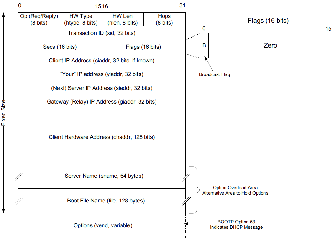
The message format is defined by BOOTP and DHCP in several RFCs ([RFC0951][RFC1542][RFC2131]).
-
The Op (Operation) field identifies the message as either a request (1) or a reply (2).
-
The HW Type (htype) field is assigned based on values used with ARP and defined in the corresponding IANA ARP parameters page [IARP], with the value 1 (Ethernet) being very common.
-
The HW Len (hlen) field gives the number of bytes used to hold the hardware (MAC) address and is commonly 6 for Ethernet-like networks.
-
The Hops field is used to store the number of relays through which the message has traveled.
The sender of the message sets this value to 0, and it is incremented at each relay.
-
The Transaction ID is a (random) number chosen by the client and copied into responses by the server.
It is used to match replies with requests.
-
The Secs field is set by the client with the number of seconds that have elapsed since the first attempt to establish or renew an address.
-
The Flags field currently contains only a single defined bit called the broadcast flag.
Clients may set this bit in requests if they are unable or unwilling to process incoming unicast IP datagrams but can process incoming broadcast datagrams (e.g., because they do not yet have an IP address).
Setting the bit informs the server and relays that broadcast addressing should be used for replies.
-
The Client IP Address (ciaddr) field includes a current IP address of the requestor, if known, and is 0 otherwise.
-
The Your IP Address (yiaddr) field is filled in by a server when providing an address to a requesting client.
-
The Next Server IP Address (siaddr) field gives the IP address of the next server to use for the client’s bootstrap process (e.g., if the client needs to download an operating system image that may be accomplished from a server other than the DHCP server).
-
The Gateway (or Relay) IP Address (giaddr) field is filled in by a DHCP or BOOTP relay with its address when forwarding DHCP (BOOTP) messages.
-
The Client Hardware Address (chaddr) field holds a unique identifier of the client and can be used in various ways by the server, including arranging for the same IP address to be given each time a particular client makes an address request.
This field has traditionally held the client’s MAC address, which has been used as an identifier.
Nowadays, the Client Identifier, an option is preferred for this use.
-
The remaining fields include the Server Name (sname) and Boot File Name (file) fields.
These fields are not always filled in, but if they are, they contain 64 or 128 bytes, respectively, of ASCII characters indicating the name of the server or path to the boot file. Such strings are null-terminated, as in the C programming language. = They can also be used instead to hold DHCP options if space is tight.
-
The final field, originally known as the Vendor Extensions field in BOOTP and fixed in length, is now known as the Options field and is variable in length.
As we shall see, options are used extensively with DHCP and are required to distinguish DHCP messages from legacy BOOTP messages.
1.3. DHCP and BOOTP Options
Given that DHCP extends BOOTP, any fields needed by DHCP that were not present when BOOTP was designed are carried as options.
-
Options take a standard format beginning with an 8-bit tag indicating the option type.
-
For some options, a fixed number of bytes following the tag contain the option value.
-
All others consist of the tag followed by 1 byte containing the length of the option value (not including the tag or length), followed by a variable number of bytes containing the option value itself.
A large number of options are available with DHCP, some of which are also supported by BOOTP.
-
The current list is given by the BOOTP/DHCP parameters page.
-
The first 77 options, including the most common ones, are specified in [RFC2132].
-
Common options include Pad (0), Subnet Mask (1), Router Address (3), Domain Name Server (6), Domain Name (15), Requested IP Address (50), Address Lease Time (51), DHCP Message Type (53), Server Identifier (54), Parameter Request List (55), DHCP Error Message (56), Lease Renewal Time (58), Lease Rebinding Time (59), Client Identifier (61), Domain Search List (119), and End (255).
The DHCP Message Type option (53) is a 1-byte-long option that is always used with DHCP messages and has the following possible values: DHCPDISCOVER (1), DHCPOFFER (2), DHCPREQUEST (3), DHCPDECLINE (4), DHCPACK (5), DHCPNAK (6), DHCPRELEASE (7), DHCPINFORM (8), DHCPFORCERENEW (9) [RFC3203], DHCPLEASEQUERY (10), DHCPLEASEUNASSIGNED (11), DHCPLEASEUNKNOWN (12), and DHCPLEASEACTIVE (13).
1.4. DHCP Protocol Operation
DHCP messages are essentially BOOTP messages with a special set of options.
-
When a new client attaches to a network, it first discovers what DHCP servers are available and what addresses they are offering.
-
It then decides which server to use and which address it desires and requests it from the offering server (while informing all the servers of its choice).
-
Unless the server has given away the address in the meantime, it responds by acknowledging the address allocation to the requesting client.
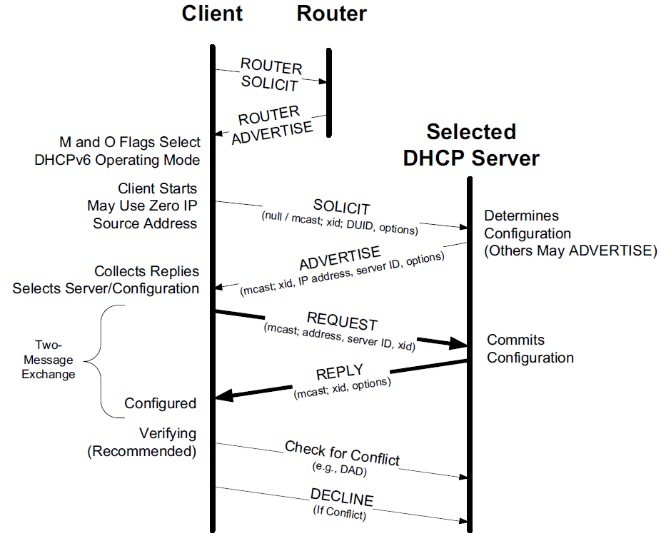
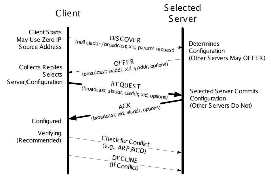 Figure 2. A typical DHCP exchange. A client discovers a set of servers and addresses they are offering using broadcast messages, requests the address it desires, and receives an acknowledgment from the selected server. The transaction ID (xid) allows requests and responses to be matched up, and the server ID (an option) indicates which server is providing and committing the provided address binding with the client. If the client already knows the address it desires, the protocol can be simplified to include use of only the REQUEST and ACK messages.
 -
Requesting clients set the BOOTP Op field to BOOTREQUEST and the first 4 bytes of the Options field to the decimal values 99, 130, 83, and 99, respectively (the magic cookie value from [RFC2132]).
-
Messages from client to server are sent as UDP/IP datagrams containing a BOOTP BOOTREQUEST operation and an appropriate DHCP message type (usually DHCPDISCOVER or DHCPREQUEST).
Such messages are sent from address 0.0.0.0 (port 68) to the limited broadcast address 255.255.255.255 (port 67).
-
Messages traveling in the other direction (from server to client) are sent from the IP address of the server and port 67 to the IP local broadcast address and port 68.
17:29:33.209909 IP (tos 0x10, ttl 16, id 0, offset 0, flags [none], proto UDP (17), length 328)
    192.168.91.254.67 > 192.168.91.130.68: BOOTP/DHCP, Reply, length 300, xid 0x3de5472b, Flags [none]
          Your-IP 192.168.91.130
          Server-IP 192.168.91.254
          Client-Ethernet-Address 00:0c:29:85:26:07
          Vendor-rfc1048 Extensions
            Magic Cookie 0x63825363
            DHCP-Message Option 53, length 1: Offer
            Server-ID Option 54, length 4: 192.168.91.254
            Lease-Time Option 51, length 4: 1800
            Subnet-Mask Option 1, length 4: 255.255.255.0
            BR Option 28, length 4: 192.168.91.255
            Default-Gateway Option 3, length 4: 192.168.91.2
            Domain-Name Option 15, length 11: "localdomain"
            Domain-Name-Server Option 6, length 4: 192.168.91.2
            Netbios-Name-Server Option 44, length 4: 192.168.91.2
It is also possible to induce a system to perform the release or acquisition of DHCP configuration information by hand. For example, in Windows the following command will release the data acquired using DHCP:
C:\> ipconfig /releaseand the following command will acquire it:
C:\> ipconfig /renewIn Linux, the following commands can be used to achieve the same results:
Linux# dhclient -rto release a DHCP lease, and
Linux# dhclientto renew one.
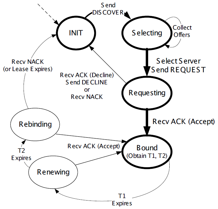
1.5. The DHCP State Machine
The DHCP protocol operates a state machine at the clients and servers. The states dictate which types of messages the protocol is expecting to process next.
1.6. DHCPv6
Although the IPv4 and IPv6 DHCP protocols achieve conceptually similar goals, their respective protocol designs and deployment options differ.
DHCPv6 [RFC3315] can be used in either a "stateful" mode, in which it works much like DHCPv4, or in a "stateless" mode in conjunction with stateless address autoconfiguration.
In the stateless mode, IPv6 clients are assumed to selfconfigure their IPv6 addresses but require additional information (e.g., DNS server address) obtained using DHCPv6. Another option exists for deriving the location of a DNS server using ICMPv6 Router Advertisement messages.
1.6.1. IPv6 Address Lifecycle
IPv6 hosts usually operate with multiple addresses per interface, and each address has a set of timers indicating how long and for what purposes the corresponding address can be used.
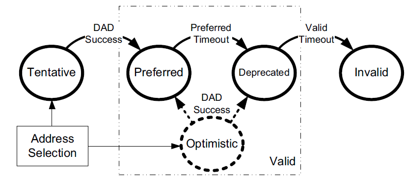
In IPv6, addresses are assigned with a preferred lifetime and valid lifetime.
These lifetimes are used to form timeouts that move an address from one state to another in an address’s state machine.
-
An address is in the preferred state when it is available for general use and is available as either a source or destination IPv6 address.
-
A preferred address becomes deprecated when its preferred timeout occurs.
When it becomes deprecated, it may still be used for existing transport (e.g., TCP) connections but is not to be used for initiating new connections.
-
When an address is first selected for use, it enters a tentative or optimistic state.
When in the tentative state, it may be used only for the IPv6 Neighbor Discovery protocol. It is not used as a source or destination address for any other purposes. While in this state the address is being checked for duplication, to see if any other nodes on the same network are already using the address. The procedure for doing this is called duplicate address detection (DAD).
An alternative to conventional DAD is called optimistic DAD [RFC4429], whereby a selected address is used for a limited set of purposes until DAD completes. Because an optimistic use of an address is really just a special set of rules for DAD, it is not a truly complete state itself. Optimistic addresses are treated as deprecated for most purposes. In particular, an address may be both optimistic and deprecated simultaneously, depending on the preferred and valid lifetimes.
1.6.2. DHCPv6 Message Format
DHCPv6 messages are encapsulated as UDP/IPv6 datagrams, with client port 546 and server port 547. Messages are sent using a host’s link-scoped source address to either relay agents or servers.
There are two message formats, one used directly between a client and a server, and another when a relay is used.
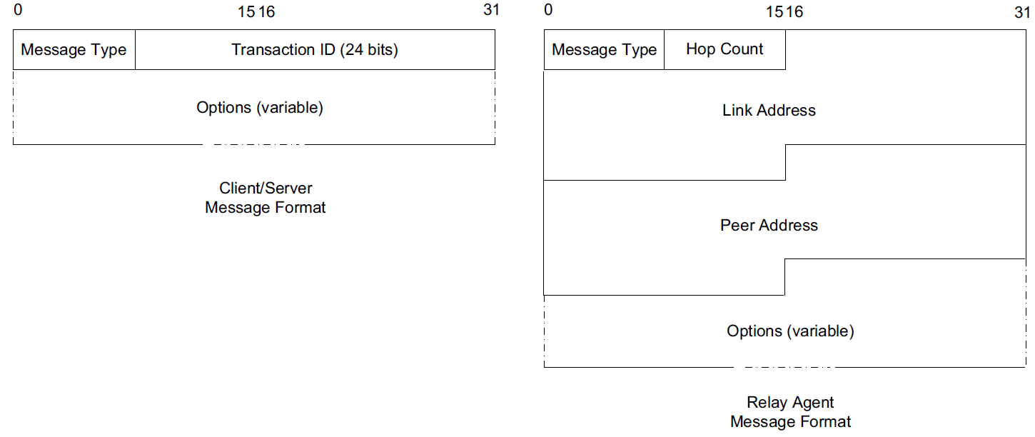
The format on the right is used between a DHCPv6 relay agent and a DHCPv6 server.
-
The Link Address field gives the global IPv6 address used by the server to identify the link on which the client is located.
-
The Peer Address field contains the address of the relay agent or client from which the message to be relayed was received.
-
Note that relaying may be chained, so a relay may be relaying a message received from another relay.
The message type for messages in the format on the left include typical DHCPstyle messages (REQUEST, REPLY, etc.), whereas the message types for messages in the format on the right include RELAY-FORW and RELAY-REPL, to indicate a message forwarded from a relay or destined to a relay, respectively. The Options field for the format on the right always includes a Relay Message option, which includes the complete message being forwarded by the relay. Other options may also be included.
One of the differences between DHCPv4 and DHCPv6 is how DHCPv6 uses IPv6 multicast addressing.
-
Clients send requests to the All DHCP Relay Agents and Servers multicast address (ff02::1:2).
-
Source addresses are of link-local scope.
In IPv6, there is no legacy BOOTP message format. The message semantics, however, are similar.
| DHCPv6 Message | DHCPv6 Value | Reference | DHCPv4 Message | Reference |
|---|---|---|---|---|
SOLICIT |
1 |
[RFC3315] |
DISCOVER |
[RFC2132] |
ADVERTISE |
2 |
[RFC3315] |
OFFER |
[RFC2132] |
REQUEST |
3 |
[RFC3315] |
REQUEST |
[RFC2132] |
CONFIRM |
4 |
[RFC3315] |
REQUEST |
[RFC2132] |
RENEW |
5 |
[RFC3315] |
REQUEST |
[RFC2132] |
REBIND |
6 |
[RFC3315] |
DISCOVER |
[RFC2132] |
REPLY |
7 |
[RFC3315] |
ACK/NAK |
[RFC2132] |
RELEASE |
8 |
[RFC3315] |
RELEASE |
[RFC2132] |
DECLINE |
9 |
[RFC3315] |
DECLINE |
[RFC2132] |
RECONFIGURE |
10 |
[RFC3315] |
FORCERENEW |
[RFC3203] |
INFORMATION-REQUEST |
11 |
[RFC3315] |
INFORM |
[RFC2132] |
RELAY-FORW |
12 |
[RFC3315] |
N/A |
|
RELAY-REPL |
13 |
[RFC3315] |
N/A |
|
LEASEQUERY |
14 |
[RFC5007] |
LEASEQUERY |
[RFC4388] |
LEASEQUERY-REPLY |
15 |
[RFC5007] |
LEASE{UNASSIGNED,UNKNOWN,ACTIVE} |
[RFC4388] |
LEASEQUERY-DONE |
16 |
[RFC5460] |
LEASEQUERYDONE |
[ID4LQ] |
LEASEQUERY-DATA |
17 |
[RFC5460] |
N/A |
|
N/A |
N/A |
N/A |
BULKLEASEQUERY |
[ID4LQ] |
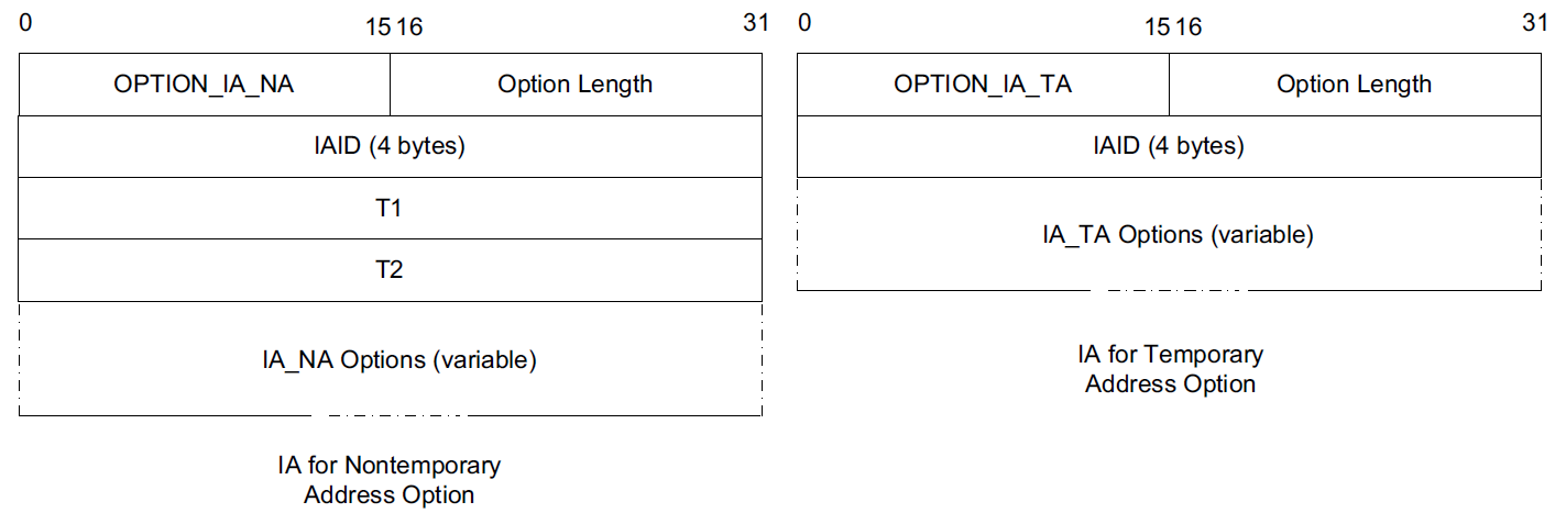
In DHCPv6, most interesting information, including addresses, lease times, location of services, and client and server identifiers, is carried in options. Two of the more important concepts used with these options are called the Identity Association (IA) and the DHCP Unique Identifier (DUID).
1.6.3. Identity Association (IA)
An Identity Association (IA) is an identifier used between a DHCP client and server to refer to a collection of addresses.
-
Each IA comprises an IA identifier (IAID) and associated configuration information.
-
Each client interface that requests a DHCPv6-assigned address requires at least one IA.
-
Each IA can be associated with only a single interface.
-
The client chooses the IAID to uniquely identify each IA, and this value is then shared with the server.
The configuration information associated with an IA includes one or more addresses and associated lease information (T1, T2, and total lease duration values).
Each address in an IA has both a preferred and a valid lifetime [RFC4862], which define the address’s lifecycle.
The types of addresses requested may be regular addresses or temporary addresses [RFC4941].
-
Temporary addresses are derived in part from random numbers to help improve privacy by frustrating the tracking of IPv6 hosts based on IPv6 addresses.
-
Temporary addresses are ordinarily assigned at the same time nontemporary addresses are assigned but are regenerated using a different random number more frequently.
When responding to a request, a server assigns one or more addresses to a client’s IA based on a set of address assignment policies determined by the server’s administrator.
Generally, such policies depend on the link on which the request arrived, standard information about the client, and other information supplied by the client in DHCP options.
1.6.4. DHCP Unique Identifier (DUID)
A DHCP Unique Identifier (DUID) identifies a single DHCPv6 client or server and is designed to be persistent over time.
It is used by servers to identify clients for the selection of addresses (as part of IAs) and configuration information, and by clients to identify the server in which they are interested.
DUIDs are variable in length and are treated as opaque values by both clients and servers for most purposes.
DUIDs are supposed to be globally unique yet easy to generate.
To satisfy these concerns simultaneously, [RFC3315] defines three different types of possible DUIDs but also mentions that these are not the only three types that might ever be created. The three types of DUIDs are as follows:
-
DUID-LLT: a DUID based on link-layer address plus time
-
DUID-EN: a DUID based on enterprise number and vendor assignment
-
DUID-LL: a DUID based on link-layer address only
1.6.5. Protocol Operation
The DHCPv6 protocol operates much like its DHCPv4 counterpart.
Whether or not a client initiates the use of DHCP is dependent on configuration options carried in an ICMPv6 Router Advertisement message the host receives.
Router advertisements include two important bit fields.
-
The M field is the Managed Address Configuration flag and indicates that IPv6 addresses can be obtained using DHCPv6.
-
The O field is the Other Configuration flag and indicates that information other than IPv6 addresses is available using DHCPv6.
Both fields, along with several others, are specified in [RFC5175].
Any combination of the M and O bit fields is possible, although having M on and O off is probably the least useful combination.
-
If both are off, DHCPv6 is not used, and address assignment takes place using stateless address autoconfiguration.
-
Having M off and O on indicates that clients should use stateless DHCPv6 and obtain their addresses using stateless address autoconfiguration.
-
Typically, a client starting out first determines what link-local address to use and performs an ICMPv6 Router Discovery operation to determine if there is a router on the attached network.
-
A router advertisement includes the M and O bit fields mentioned previously.
-
If DHCPv6 is in use, at least the M bit field is set and the client multicasts the DHCPSOLICIT message to find DHCPv6 servers.
-
A response comes in the form of one or more DHCPADVERTISE messages, indicating the presence of at least one DHCPv6 server.
These messages constitute two of the so-called four-message exchange operations of DHCPv6.
In cases where the location of a DHCPv6 server is already known or an address need not be allocated (e.g., stateless DHCPv6 or the Rapid Commit option is being used), the four-message exchange can be shortened to become a two-message exchange, in which case only the REQUEST and REPLY messages are used.
A DHCPv6 server commits a binding formed from the combination of a DUID, IA type (temporary, nontemporary, or prefix), and IAID. The IAID is a 32-bit number chosen by the client.
Each binding can have one or more leases, and one or more bindings can be manipulated using a single DHCPv6 transaction.
-
DAD for the client system’s link-local address is a Neighbor Solicitation for its own IPv6 address.
00:0c:29:85:26:11 > 33:33:ff:85:26:11, ethertype IPv6 (0x86dd), length 86: (hlim 255, next-header ICMPv6 (58) payload length: 32) :: > ff02::1:ff85:2611: [icmp6 sum ok] ICMP6, neighbor solicitation, length 32, who has fe80::20c:29ff:fe85:2611
      unknown option (14), length 8 (1):
        0x0000:  93d1 208a 5c73
The packet is sent to the corresponding solicited-node address ff02::1:ff85:2611. It optimistically assumes that this address is not otherwise in use on the link, so it continues on immediately with a Router Solicitation (RS).
-
The Router Solicitation induces a nearby router to provide a Router Advertisement.
The solicitation message is sent to the All Routers address (ff02::2). It induces each router on the network to respond with a Router Advertisement (RA), which carries the important M and O bits the client requires to determine what to do next.
00:0c:29:85:26:11 > 33:33:00:00:00:02, ethertype IPv6 (0x86dd), length 70: (hlim 255, next-header ICMPv6 (58) payload length: 16) fe80::20c:29ff:fe85:2611 > ff02::2: [icmp6 sum ok] ICMP6, router solicitation, length 16
      source link-address option (1), length 8 (1): 00:0c:29:85:26:11
        0x0000:  000c 2985 2611
1.7. Rapid Commit
The DHCP Rapid Commit option [RFC4039] allows a DHCP server to respond to the DHCPDISCOVER message with a DHCPACK, effectively skipping the DHCPREQUEST message and ultimately using a two-message exchange instead of a four-message exchange.
The motivation for this option is to quickly configure hosts that may change their point of network attachment frequently (i.e., mobile hosts).
When only a single DHCP server is available and addresses are plentiful, this option should be of no significant concern.
2. Stateless Address Autoconfiguration (SLAAC)
While most routers have their addresses configured manually, hosts can be assigned addresses manually, using an assignment protocol like DHCP, or automatically using some sort of algorithm.
There are two forms of automatic assignment, depending on what type of address is being formed.
-
For addresses that are to be used only on a single link (link-local addresses), a host need only find some appropriate address not already in use on the link.
-
For addresses that are to be used for global connectivity, however, some portion of the address must generally be managed.
There are mechanisms in both IPv4 and IPv6 for link-local address autoconfiguration, whereby a host determines its address(es) largely without help. This is called stateless address autoconfiguration (SLAAC).
2.1. Dynamic Configuration of IPv4 Link-Local Addresses
In cases where a host without a manually configured address attaches to a network lacking a DHCP server, IP-based communication is unable to take place unless the host somehow generates an IP address to use.
-
[RFC3927] describes a mechanism whereby a host can automatically generate its own IPv4 address from the link-local range 169.254.1.1 through 169.254.254.254 using the 16-bit subnet mask 255.255.0.0 (see [RFC5735]).
This method is known as dynamic link-local address configuration or Automatic Private IP Addressing (APIPA).
-
In essence, a host selects a random address in the range to use and checks to see if that address is already in use by some other system on the subnetwork.
This check is implemented using IPv4 ACD.
2.2. IPv6 SLAAC for Link-Local Addresses
The goal of IPv6 SLAAC is to allow nodes to automatically (and autonomously) self-assign link-local IPv6 addresses.
IPv6 SLAAC is described in [RFC4862]. It involves three major steps: obtaining a link-local address, obtaining a global address using stateless autoconfiguration, and detecting whether the link-local address is already in use on the link.
Stateless autoconfiguration can be used without routers, in which case only link-local addresses are assigned.
When routers are present, a global address is formed using a combination of the prefix advertised by a router and locally generated information.
SLAAC can also be used in conjunction with DHCPv6 (or manual address assignment) to allow a host to obtain information in addition to its address (called stateless DHCPv6).
Hosts that perform SLAAC can be used on the same network as those configured using stateful or stateless DHCPv6.
Generally, stateful DHCPv6 is used when finer control is required in assigning address to hosts, but it is expected that stateless DHCPv6 in combination with SLAAC will be the most common deployment option.
In IPv6, tentative (or optimistic) link-local addresses are selected using procedures specified in [RFC4291] and [RFC4941]. They apply only to multicast-capable networks and are assigned infinite preferred and valid lifetimes once established.
To form the numeric address, a unique number is appended to the well-known link-local prefix fe80::0 (of appropriate length). This is accomplished by setting the right-most N bits of the address to be equal to the (N-bit-long) number, the left-most bits equal to the 10-bit link-local prefix 1111111010, and the rest to 0. The resulting address is placed into the tentative (or optimistic) state and checked for duplicates.
2.3. IPv6 Duplicate Address Detection (DAD)
IPv6 DAD uses ICMPv6 Neighbor Solicitation and Neighbor Advertisement messages to determine if a particular (tentative or optimistic) IPv6 address is already in use on the attached link.
If a duplicate address is discovered, the procedure causes the tentative address to not be used.
If DAD succeeds, the tentative address transitions to the preferred state and can be used without restriction.
DAD is performed as follows:
-
A node first joins the All Nodes multicast address and the Solicited-Node multicast address of the tentative address.
-
To check for use of an address duplicate, a node sends one or more ICMPv6 Neighbor Solicitation messages.
The source and destination IPv6 addresses of these messages are the unspecified address and Solicited-Node address of the target address being checked, respectively.
The Target Address field is set to the address being checked (the tentative address).
-
If a Neighbor Advertisement message is received in response, DAD has failed, and the address being checked is abandoned.
|
As a consequence of joining multicast groups, MLD messages are sent, but their transmission is delayed by a random interval according to [RFC4862] to avoid congesting the network when many nodes simultaneously join the All Hosts group (e.g., after a restoration of power). For DAD, these MLD messages are used to inform MLD-snooping switches to forward multicast traffic as necessary. |
When an address has not yet successfully completed DAD, any received neighbor solicitations for it are treated in a special way, as this is indicative of some other host’s intention to use the same address. If such messages are received, they are dropped, the current tentative address is abandoned, and DAD fails.
If DAD fails, by receiving a similar neighbor solicitation from another node or a neighbor advertisement for the target address, the address is not assigned to an interface and does not become a preferred address. If the address is a link-local address being configured based on an interface identifier derived from a local MAC address, it is unlikely that the same procedure will ultimately produce a nonconflicting address, so the use of this address is abandoned and administrator input is required. If the address is based on a different form of interface identifier, IPv6 operations may be retried using another address based on an alternative tentative address.
2.4. IPv6 SLAAC for Global Addresses
Once a node has acquired a link-local address, it is likely to require one or more global addresses as well.
Global addresses are formed using a process similar to that for link-local SLAAC but using a prefix provided by a router.
-
Such prefixes are carried in the Prefix option of a router advertisement, and a flag indicates whether the prefix should be used in forming global addresses with SLAAC.
-
If so, the prefix is combined with an interface identifier (e.g., the same one used in forming a link-local address if the privacy extension is not being used) to form a global address.
-
The preferred and valid lifetimes of such addresses are also determined by information present in the Prefix option.
3. PPP over Ethernet (PPPoE)
For most LANs and some WAN connections, DHCP provides the most common method for configuring client systems.
For WAN connections such as DSL, another method based on PPP is often used instead.
-
This method involves carrying PPP on Ethernet and is called PPP over Ethernet (PPPoE).
-
PPPoE is used in cases where the WAN connection device (e.g., DSL modem) acts as a switch or bridge instead of a router.
-
PPP is preferred as a basis for establishing connectivity by some ISPs because it may provide finer-grain configuration control and audit logs than other configuration options such as DHCP.
-
To provide Internet connectivity, some device such as a user’s PC must implement the IP routing and addressing functions.
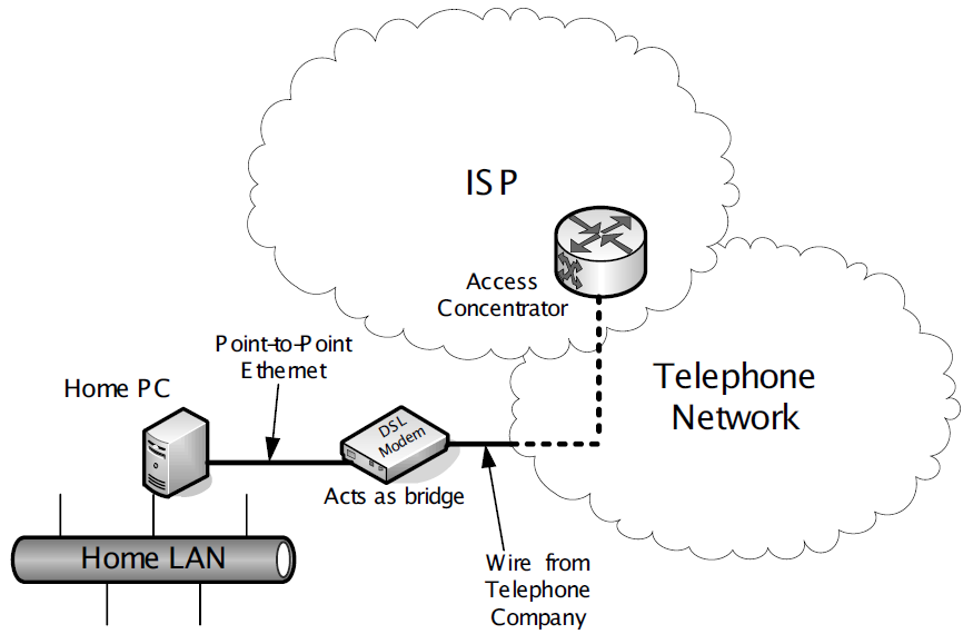 Figure 8. A simplified view of DSL service using PPPoE as provided to a customer. The home PC implements the PPPoE protocol and authenticates the subscriber with the ISP. It may also act as a router, DHCP server, DNS server, and/or NAT device for the home LAN.
DSL provides a point-to-point digital link that can operate simultaneously with a conventional analog telephone line (called plain old telephone service or POTS).
-
This simultaneous use of the customer’s physical phone wires is accomplished using frequency division multiplexing—the DSL information is carried on higher frequencies than POTS.
-
A filter is required when attaching conventional telephone handsets to avoid interference from the higher DSL frequencies.
-
The DSL modem effectively provides a bridged service to a PPP port on the ISP’s access concentrator (AC), which interconnects the customer’s modem line and the ISP’s networking equipment.
-
The modem and AC also support the PPPoE protocol, which the user has elected in this example to configure on a home PC attached to the DSL modem using a point-to-point Ethernet network (i.e., an Ethernet LAN using only a single cable).