TCP/IP: Name Resolution and the Domain Name System (DNS)
- 1. The DNS Name Space
- 2. Name Servers and Zones
- 3. Caching
- 4. The DNS Protocol
- 5. Sort Lists, Round-Robin, and Split DNS
- 6. Open DNS Servers and DynDNS
- 7. LLMNR and mDNS
- References
IP addresses (especially IPv6 addresses) are cumbersome for humans to use and remember, so the Internet supports the use of host names to identify hosts, both clients and servers.
In order to be used by protocols such as TCP and IP, host names are converted into IP addresses using a process known as name resolution.
There are different forms of name resolution in the Internet, but the most prevalent and important one uses a distributed database system known as the Domain Name System (DNS) .
DNS is a distributed client/server networked database that is used by TCP/IP applications to map between host names and IP addresses (and vice versa).
-
DNS runs as an application on the Internet, using IPv4 or IPv6 (or both).
-
For scalability, DNS names are hierarchical, as are the servers that support name resolution.
From an application’s point of view, access to the DNS is through an application library called a resolver.
-
In general, an application must convert a host name to an IPv4 and/or IPv6 address before it can ask TCP to open a connection or send a unicast datagram using UDP.
-
The TCP and IP protocol implementations know nothing about the DNS; they operate only with the addresses.
1. The DNS Name Space
The set of all names used with DNS constitutes the DNS name space. This space is partitioned hierarchically and is case insensitive, similar to computer file system folders (directories) and files.
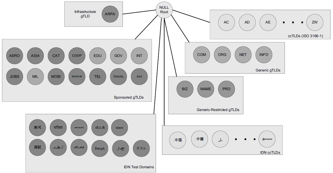
The current DNS name space is a tree of domains with an unnamed root at the top. The top echelons of the tree are the so-called top-level domains (TLDs), which include
-
generic TLDs (gTLDs),
-
country-code TLDs (ccTLDs),
-
and internationalized country-code TLDs (IDN ccTLDs), plus a special infrastructure TLD called,
-
for historical reasons, ARPA [RFC3172].
| Domain | Purpose | Reference |
|---|---|---|
intranet. |
Used for Private/internal DNS Namespaces |
RFC 6762 (Appendix G) |
internal. |
||
private. |
||
corp. |
||
home. |
||
lan. |
||
local. |
Used for Multicast DNS as link-local host names |
RFC 6762 (Section 3) |
localhost. |
Reserved to avoid conflict with the traditional use of localhost as a hostname |
RFC 6761 |
onion. |
Anonymous onion service |
RFC 7686 |
-
RFC 6762 reserves the use of .local for link-local host names that can be resolved via the Multicast DNS name resolution protocol.
-
RFC 7686 reserves the use of .onion for the self-authenticating names of Tor onion services.
1.1. DNS Naming Syntax
The names below a TLD in the DNS name tree are further partitioned into groups known as subdomains. This is very common practice, especially for the ccTLDs.
For example, the site www.ci.manhattan-beach.ca.us is the site of Manhattan Beach, California’s, city government in the United States, also known as fully qualified domain names (FQDNs).
-
FQDNs are sometimes written more formally with a trailing period (e.g., mit.edu.).
-
The trailing period indicates that the name is complete; no additional information should be added to the name when performing a name resolution.
In contrast to the FQDN, an unqualified domain name, which is used in combination with a default domain or domain search list set during system configuration, has one or more strings appended to the end.
-
When a system is configured, it is typically assigned a default domain extension and search list using DHCP (or, less commonly, the RDNSS and DNSSL RA options).
For example, the default domain cs.berkeley.edu might be configured in systems at the computer science department at UC Berkeley.
If a user on one of these machines types in the name vangogh, the local resolver software converts this name to the FQDN vangogh.cs.berkeley.edu. before invoking a resolver to determine vangogh’s IP address.
A domain name consists of a sequence of labels separated by periods.
-
The name represents a location in the name hierarchy, where the period is the hierarchy delimiter and descending down the tree takes place from right to left in the name.
-
Each label can be up to 63 characters long, and an entire FQDN is limited to at most 255 (1-byte) characters.
The hierarchical structure of the DNS name space allows different administrative authorities to manage different parts of the name space. For example,
-
creating a new DNS name of the form elevator.cs.berkeley.edu would likely require dealing with the owner of the cs.berkeley.edu subdomain only.
-
The berkeley .edu and edu portions of the name space would not require alteration, so the owners of those would not need to be bothered.
-
This feature of DNS is one key aspect of its scalability.
2. Name Servers and Zones
Management responsibility for portions of the DNS name space is assigned to individuals or organizations.
-
The active DNS name space (domains) is supposed to arrange for at least two name servers or DNS servers to hold information about the name space so that users of the Internet can perform queries on the names.
-
The collection of servers forms the DNS (service) itself, a distributed system whose primary job is to provide name-to-address mappings.
The unit of administrative delegation, in the language of DNS servers, is called a zone.
-
A zone is a subtree of the DNS name space that can be administered separately from other zones.
-
Every domain name exists within some zone, even the TLDs that exist in the root zone.
-
Whenever a new record is added to a zone, the DNS administrator for the zone allocates a name and additional information (usually an IP address) for the new entry and enters these into the name server’s database.
A DNS server can contain information for more than one zone.
-
At any hierarchical change point in a domain name (i.e., wherever a period appears), a different zone and containing server may be accessed to provide information for the name. This is called a delegation.
-
Each zone has a designated owner or responsible party who is given authority to manage the names, addresses, and subordinate zones, also the name servers that contain the zone’s database(s) within the zone.
Zone information is supposed to exist in at least two places, implying that there should be at least two servers containing information for each zone.
-
This is for redundancy; if one server is not functioning properly, at least one other server is available.
-
All of these servers contain identical information about a zone.
-
Typically, among the servers, a primary server contains the zone database in a disk file, and one or more secondary servers obtain copies of the database in its entirety from the primary using a process called a zone transfer.
3. Caching
Name servers contain information such as name-to-IP-address mappings that may be obtained from three sources.
-
The name server obtains the information directly from the zone database,
The server is said to contain authoritative information about the zone and may be called an authoritative server for the zone. Such servers are identified by name within the zone information.
-
as the result of a zone transfer (e.g., for a slave server),
-
or from another server in the course of processing a resolution.
Most name servers (except some of the root and TLD servers) also cache zone information they learn, up to a time limit called the time to live (TTL). They use this cached information to answer queries.
-
Doing so can greatly decrease the amount of DNS message traffic that would otherwise be carried on the Internet.
-
When answering a query, a server indicates whether the information it is returning has been derived from its cache or from its authoritative copy of the zone.
-
When cached information is returned, it is common for a server to also include the domain names of the name servers that can be contacted to retrieve authoritative information about the corresponding zone.
It is worth mentioning that caching is applied both for successful resolutions and for unsuccessful resolutions (called negative caching).
-
If a request for a particular domain name fails to return a record, this fact is also cached.
-
Doing so can help to reduce Internet traffic when errant applications repeatedly make requests for names that do not exist.
-
Negative caching was changed from optional to mandatory by [RFC2308].
In some network configurations (e.g., those using older UNIX-compatible systems), the cache is maintained in a nearby name server, not in the resolvers resident in the clients.
-
Placing the cache in the server allows any hosts on the LAN that use the nearby server to benefit from the server’s cache but implies a small delay in accessing the cache over the local network.
-
In Windows and more recent systems (e.g., Linux), the client can maintain a cache, and it is made available to all applications running on the same system.
In Windows, this happens by default, and in Linux, it is a service that can be enabled or disabled.
-
On Windows, the local system’s cache parameters may be modified by editing the following registry entry:
HKLM\SYSTEM\CurrentControlSet\Services\DNSCache\ParametersThe DWORD value MaxNegativeCacheTtl gives the maximum number of seconds that a negative DNS result remains in the resolver cache.
The DWORD value MaxCacheTtl gives the maximum number of seconds that a DNS record may remain in the resolver cache.
If this value is less than the TTL of a received DNS record, the lesser value controls how long the record remains in cache.
These two registry keys do not exist by default, so they must be created in order to be used.
-
In Linux and other systems that support it, the Name Service Caching Daemon (NSCD) provides a client-side caching capability.
It is controlled by the /etc/nscd.conf file that can indicate which types of resolutions (for DNS and some other services) are cached, along with some cache parameters such as TTL settings.
In addition, the file /etc/nsswitch.conf controls how name resolution for applications takes place. Among other things, it can control whether local files, the DNS protocol, and/or NSCD is employed for mappings.
4. The DNS Protocol
The DNS protocol consists of two main parts:
-
a query/response protocol used for performing queries against the DNS for particular names,
-
and another protocol for name servers to exchange database records (zone transfers).
-
It also has a way to notify secondary servers that the zone database has evolved and a zone transfer is necessary (DNS Notify), and a way to dynamically update the zone (dynamic updates).
DNS query/response operations are supported over the distributed DNS infrastructure consisting of
-
servers deployed locally at each site or ISP,
-
and a special set of root servers,
-
also a special set of generic top-level domain servers used for scaling some of the larger gTLDs.
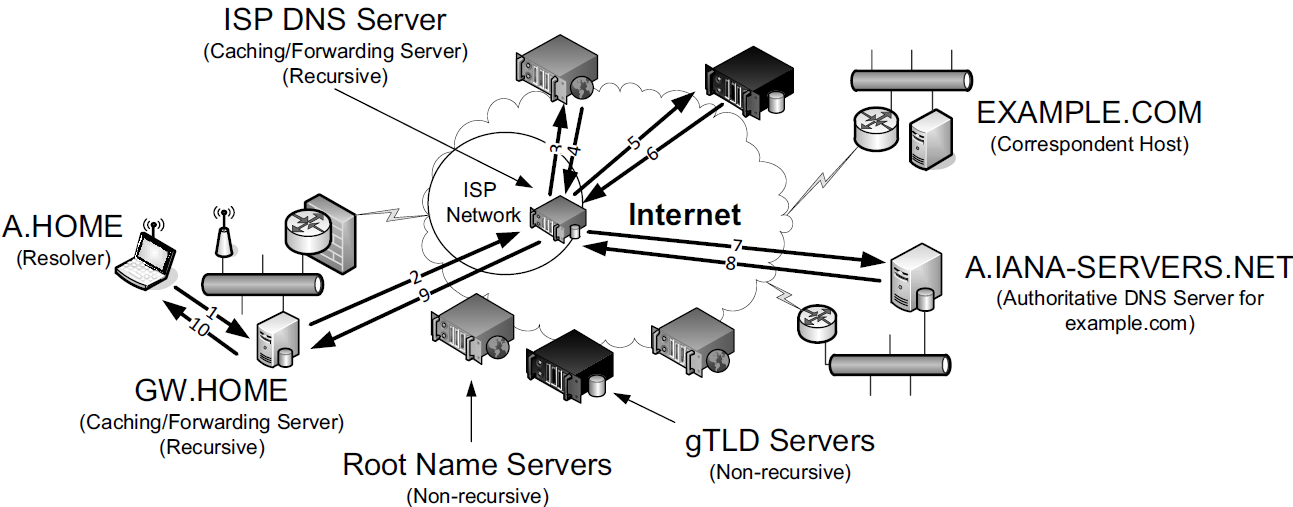
EXAMPLE.COM from A.HOME involves up to ten messages. The local recursive server (GW.HOME here) uses a DNS server provided by its ISP. That server, in turn, uses an Internet root name server and a gTLD server (for COM and NET TLDs) to find the name server for the EXAMPLE.COM domain. That name server (A.IANA-SERVERS.NET here) provides the required IP address for the host EXAMPLE.COM. All of the recursive servers cache any information learned for later use.Here, we have a laptop called A.HOME residing nearby the DNS server GW.HOME. The domain HOME is private, so it is not known to the Internet—only locally at the user’s residence.
When A.HOME wishes to connect to the host EXAMPLE.COM, it must determine the IP address of EXAMPLE.COM.
-
Assuming it does not know this address already, the resolver software on A.HOME first makes a request to its local name server, GW.HOME, to convert the name EXAMPLE.COM into an address and constitutes message 1.
-
If GW.HOME does not already know the IP address for EXAMPLE.COM or the name servers for either the EXAMPLE.COM domain or the COM TLD, it forwards the request to another DNS server (called recursion). In this case, a request (message 2) goes to an ISP-provided DNS server.
-
Assuming that this server also does not know the required address or other information, it contacts one of the root name servers (message 3).
-
The root servers are not recursive, so they do not process the request further but instead return the information required to contact a name server for the COM TLD.
For example, it might return the name A.GTLD-SERVERS.NET and one or more of its IP addresses (message 4).
-
With this information, the ISP-provided server contacts the gTLD server (message 5) and discovers the name and IP addresses of the name servers for the domain EXAMPLE.COM (message 6). In this case, one of the servers is A.IANA-SERVERS.NET.
-
Given the correct server for the domain, the ISP-provided server contacts the appropriate server (message 7), which responds with the requested IP address (message 8).
-
At this point, the ISP-provided server can respond to GW.HOME with the required information (message 9).
-
GW.HOME is now able to complete the initial query and responds to the client with the desired IPv4 and/or IPv6 address(es) (message 10).
From the perspective of A.HOME, the local name server was able to perform the request.
However, what really happened is a recursive query, where the GW.HOME and ISP-provided servers in turn made additional DNS requests to satisfy A.HOME's query.
-
In general, most name servers perform recursive queries such as this.
-
The notable exceptions are the root servers and other TLD servers that do not perform recursive queries.
4.1. DNS Message Format
There is one basic DNS message format [RFC6195] used for all DNS operations (queries, responses, zone transfers, notifications, and dynamic updates).
The basic DNS message begins with a fixed 12-byte header followed by four variable-length sections:
-
questions (or queries),
-
answers,
-
authority records,
-
and additional records.
All but the first section contain one or more resource records (RRs). The question section contains a data item that is very close in structure to an RR. RRs can be cached; questions are not.
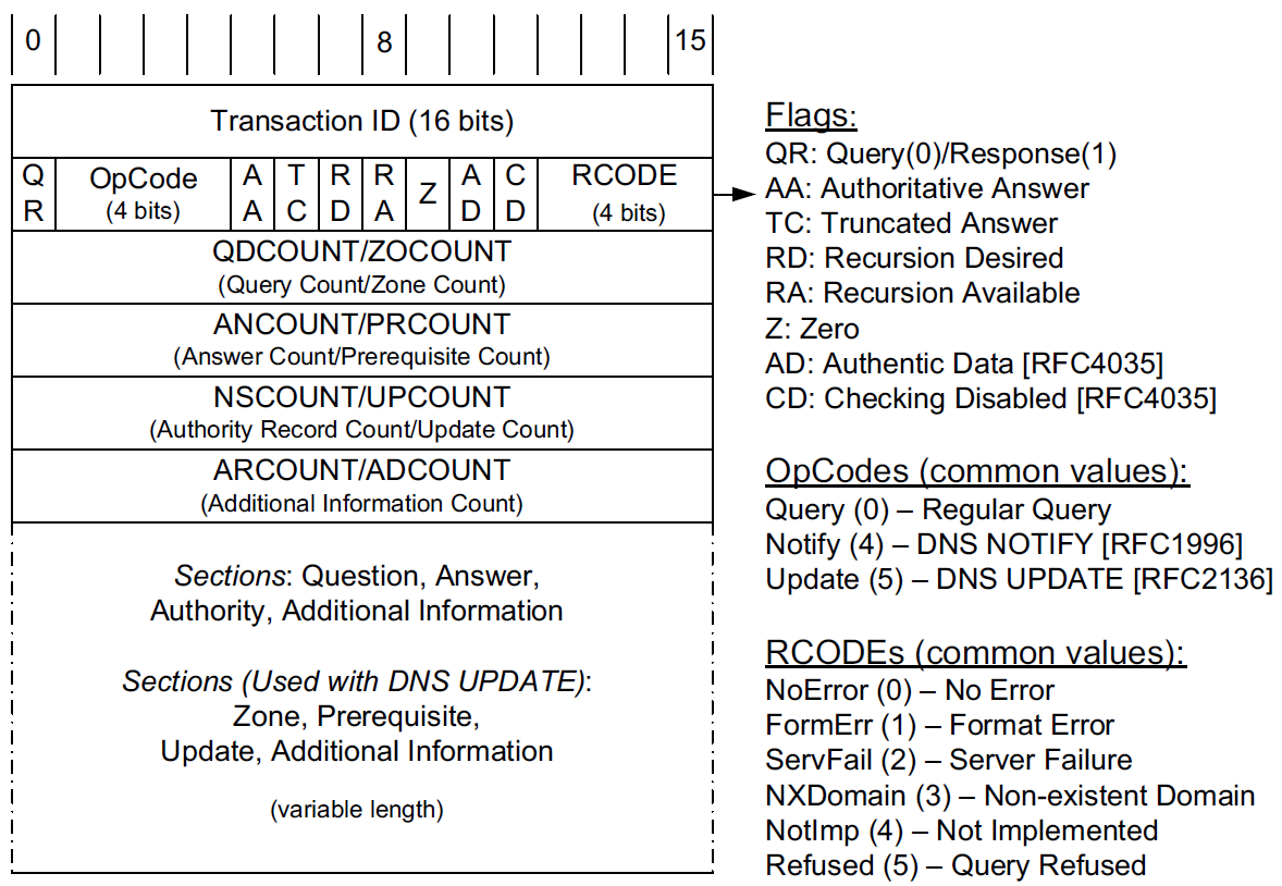
In the fixed-length header, the Transaction ID field is set by the client and returned by the server. It lets the client match responses to requests.
The second 16-bit word includes a number of flags and other subfields.
-
Beginning from the left-most bit, QR is a 1-bit field: 0 means the message is a query; 1 means it is a response.
-
The next is the OpCode, a 4-bit field.
The normal value is 0 (a standard query) for requests and responses.
Other values are: 4 (notify), and 5 (update).
Other values (1–3) are deprecated or never seen in operational use.
-
Next is the AA bit field that indicates an "authoritative answer" (as opposed to a cached answer).
-
TC is a 1-bit field that means "truncated."
With UDP, this flag being set means that the total size of the reply exceeded 512 bytes, and only the first 512 bytes of the reply were returned.
-
RD is a bit field that means "recursion desired."
It can be set in a query and is then returned in the response. It tells the server to perform a recursive query.
If the bit is not set, and the requested name server does not have an authoritative answer, the requested name server returns a list of other name servers to contact for the answer. At this point, the overall query may be continued by contacting the list of other name servers. This is called an iterative query.
-
RA is a bit field that means "recursion available."
This bit is set in the response if the server supports recursion.
Root servers generally do not support recursion, thereby forcing clients to perform iterative queries to complete name resolution.
-
The Z bit field must be 0 for now but is reserved for future use.
-
The AD bit field is set to true if the contained information is authenticated, and the CD bit is set to true if security checking is disabled.
-
The Response Code (or RCODE) field is a 4-bit field with the return code whose possible values are given in [DNSPARAM].
The common values include 0 (no error) and 3 (name error or "nonexistent domain", written as NXDOMAIN).
A name error is returned only from an authoritative name server and means that the domain name specified in the query does not exist.
-
The next four fields are 16 bits in size and specify the number of entries in the question, answer, authority, and additional information sections that complete the DNS message.
For a query, the number of questions is normally 1 and the other three counts are 0. For a reply, the number of answers is at least 1. Questions have a name, type, and class.
All of the other sections contain zero or more RRs. RRs contain a name, type, and class information, but also the TTL value that controls how long the data can be cached.
x@node-0:~$ dig @8.8.8.8 +nocmd +trace +question cs.berkeley.edu A
;.				IN	NS
.			12283	IN	NS	g.root-servers.net.
.			12283	IN	NS	j.root-servers.net.
.			12283	IN	NS	e.root-servers.net.
.			12283	IN	NS	l.root-servers.net.
.			12283	IN	NS	d.root-servers.net.
.			12283	IN	NS	a.root-servers.net.
.			12283	IN	NS	b.root-servers.net.
.			12283	IN	NS	i.root-servers.net.
.			12283	IN	NS	m.root-servers.net.
.			12283	IN	NS	h.root-servers.net.
.			12283	IN	NS	c.root-servers.net.
.			12283	IN	NS	k.root-servers.net.
.			12283	IN	NS	f.root-servers.net.
.			12283	IN	RRSIG	NS 8 0 518400 20221223170000 20221210160000 18733 . RKkv+/2Kd7pxDEzR/ZHRsgPe+YM/M3BYXrU/WwOaco4UT9Wc3A2CF+Bd rBlNbvi8fS7MXDeQPZfRPrVn1yLVNTNVJJVCDzge5QKVhumVM6zfB60e aI0a0mojthg7cKS9mZa29cvoITNW41MTk4dilaDKl4uvLfjnfvZ59ZBS BgDHvd8e0VC53v7Dz8fnoo+climQvU51Xq6haB/v3/m8RXCm6Yvu2qg5 xLdZaRHrnFqKFur7+7UE7zMqWVA1rmwozEi/mgfK0JczDk9LJ2xyEgRH Cq+wKVAZEVU48Yoe1Vemh2PwTZqBLnXpKHooMQ4tNNAkAYKMnP5Na8oW 2U/Y7A==
;; Received 525 bytes from 8.8.8.8#53(8.8.8.8) in 39 ms

;cs.berkeley.edu.		IN	A
edu.			172800	IN	NS	a.edu-servers.net.
edu.			172800	IN	NS	h.edu-servers.net.
edu.			172800	IN	NS	b.edu-servers.net.
edu.			172800	IN	NS	d.edu-servers.net.
edu.			172800	IN	NS	c.edu-servers.net.
edu.			172800	IN	NS	l.edu-servers.net.
edu.			172800	IN	NS	f.edu-servers.net.
edu.			172800	IN	NS	e.edu-servers.net.
edu.			172800	IN	NS	i.edu-servers.net.
edu.			172800	IN	NS	g.edu-servers.net.
edu.			172800	IN	NS	k.edu-servers.net.
edu.			172800	IN	NS	j.edu-servers.net.
edu.			172800	IN	NS	m.edu-servers.net.
edu.			86400	IN	DS	28065 8 2 4172496CDE85534E51129040355BD04B1FCFEBAE996DFDDE652006F6 F8B2CE76
edu.			86400	IN	RRSIG	DS 8 1 86400 20221224170000 20221211160000 18733 . p7OvKwfjcx6Iveh7NZ0huq24niVZINxiqttjuDxDJD3wNwVdmgvxzBrw +VzP+5p6JJ63okmvaqlJYlZJNX85n7vweab/LAPFFtT2kHs77Zc/MY1a k/k/E/mZstyAkoS3JwXoDvStoCdAUU/8eH32DFROPpZsKjoeiejcWOWb 86yBU7QKjPlsu5BJO74qlyDP7yLlEBum5YbcMDGoaV3RPozrTCz7r1+V KItG7ObBnw9Vjchv6gG3Q7wyTw2uXWMfGBgAS6P8VGN/GgqS7Bct9y+v 1cc75EY7YM0pqtzu230m1DFnBUWG1pcU4+fS5kPmUBpyBxpMFO99q48q IJyk2A==
;; Received 1205 bytes from 192.36.148.17#53(i.root-servers.net) in 55 ms

;cs.berkeley.edu.		IN	A
berkeley.edu.		172800	IN	NS	adns1.berkeley.edu.
berkeley.edu.		172800	IN	NS	adns2.berkeley.edu.
berkeley.edu.		172800	IN	NS	adns3.berkeley.edu.
berkeley.edu.		86400	IN	DS	38028 10 2 A37654ABBF41A2F3D7DC8D4B2E77A70E9B1AF6A670101FF8AEF4F36E FB7CA323
berkeley.edu.		86400	IN	DS	20949 10 2 448D22499ED0D3098E2BC186F5D5F5091055C5BECDF3BD82632855D2 1CD493C4
berkeley.edu.		86400	IN	RRSIG	DS 8 2 86400 20221216073252 20221209062252 28775 edu. ym6j4W1W9h8oaqJMFu1kZ/eTHWiRh94zTP33PU81PCP2JGjiKxXNC27D oPU96kj6hWv9jYCLKFqtjcMjdFb/KJL3JmJNBl4QTf9RNHfXyxEsd7zm RgVJkgk5XBaCebMzZsJWz6godVrxGtLC8EcRCg+Y3IQeDLmS5T+zUtaZ GR8kYgN9L+mW23jrKTVh2rOD+v1AZu0fbitcfj/3Q25odQ==
;; Received 471 bytes from 192.35.51.30#53(f.edu-servers.net) in 79 ms

;cs.berkeley.edu.		IN	A
cs.berkeley.edu.	86400	IN	A	23.185.0.1
;; Received 88 bytes from 128.32.136.14#53(adns2.berkeley.edu) in 223 ms
x@node-0:~$ sudo tcpdump -tnv udp and port 53
IP (tos 0x0, ttl 64, id 2498, offset 0, flags [none], proto UDP (17), length 68)
192.168.91.128.50158 > 8.8.8.8.53: 30713+ [1au] NS? . (40)
IP (tos 0x0, ttl 128, id 2372, offset 0, flags [none], proto UDP (17), length 553)
8.8.8.8.53 > 192.168.91.128.50158: 30713$ 14/0/1 . NS a.root-servers.net., . NS b.root-servers.net., . NS c.root-servers.net., . NS d.root-servers.net., . NS e.root-servers.net., . NS f.root-servers.net., . NS g.root-servers.net., . NS h.root-servers.net., . NS i.root-servers.net., . NS j.root-servers.net., . NS k.root-servers.net., . NS l.root-servers.net., . NS m.root-servers.net., . RRSIG (525)
IP (tos 0x0, ttl 64, id 1382, offset 0, flags [DF], proto UDP (17), length 64)
192.168.91.128.43221 > 192.168.91.2.53: 64354+ A? a.root-servers.net. (36)
IP (tos 0x0, ttl 64, id 1383, offset 0, flags [DF], proto UDP (17), length 64)
192.168.91.128.43221 > 192.168.91.2.53: 43153+ AAAA? a.root-servers.net. (36)
IP (tos 0x0, ttl 128, id 2373, offset 0, flags [none], proto UDP (17), length 80)
192.168.91.2.53 > 192.168.91.128.43221: 64354 1/0/0 a.root-servers.net. A 198.41.0.4 (52)
IP (tos 0x0, ttl 128, id 2374, offset 0, flags [none], proto UDP (17), length 92)
192.168.91.2.53 > 192.168.91.128.43221: 43153 1/0/0 a.root-servers.net. AAAA 2001:503:ba3e::2:30 (64)
...
IP (tos 0x0, ttl 128, id 2397, offset 0, flags [none], proto UDP (17), length 80)
192.168.91.2.53 > 192.168.91.128.45991: 10021 1/0/0 m.root-servers.net. A 202.12.27.33 (52)
IP (tos 0x0, ttl 128, id 2398, offset 0, flags [none], proto UDP (17), length 92)
192.168.91.2.53 > 192.168.91.128.45991: 22347 1/0/0 m.root-servers.net. AAAA 2001:dc3::35 (64)
IP (tos 0x0, ttl 64, id 49461, offset 0, flags [none], proto UDP (17), length 84)
192.168.91.128.37889 > 198.97.190.53.53: 53008 [1au] A? cs.berkeley.edu. (56)
IP (tos 0x0, ttl 128, id 2399, offset 0, flags [none], proto UDP (17), length 1202)
198.97.190.53.53 > 192.168.91.128.37889: 53008- 0/15/27 (1174)
IP (tos 0x0, ttl 64, id 43388, offset 0, flags [DF], proto UDP (17), length 63)
192.168.91.128.44873 > 192.168.91.2.53: 35146+ A? a.edu-servers.net. (35)
IP (tos 0x0, ttl 64, id 43389, offset 0, flags [DF], proto UDP (17), length 63)
192.168.91.128.44873 > 192.168.91.2.53: 21077+ AAAA? a.edu-servers.net. (35)
IP (tos 0x0, ttl 128, id 2400, offset 0, flags [none], proto UDP (17), length 79)
192.168.91.2.53 > 192.168.91.128.44873: 35146 1/0/0 a.edu-servers.net. A 192.5.6.30 (51)
IP (tos 0x0, ttl 128, id 2401, offset 0, flags [none], proto UDP (17), length 91)
192.168.91.2.53 > 192.168.91.128.44873: 21077 1/0/0 a.edu-servers.net. AAAA 2001:503:a83e::2:30 (63)
...
IP (tos 0x0, ttl 128, id 2424, offset 0, flags [none], proto UDP (17), length 91)
192.168.91.2.53 > 192.168.91.128.56144: 60038 1/0/0 m.edu-servers.net. AAAA 2001:501:b1f9::30 (63)
IP (tos 0x0, ttl 128, id 2425, offset 0, flags [none], proto UDP (17), length 79)
192.168.91.2.53 > 192.168.91.128.56144: 900 1/0/0 m.edu-servers.net. A 192.55.83.30 (51)
IP (tos 0x0, ttl 64, id 37599, offset 0, flags [none], proto UDP (17), length 84)
192.168.91.128.59416 > 192.31.80.30.53: 47106 [1au] A? cs.berkeley.edu. (56)
IP (tos 0x0, ttl 128, id 2426, offset 0, flags [none], proto UDP (17), length 499)
192.31.80.30.53 > 192.168.91.128.59416: 47106- 0/6/5 (471)
IP (tos 0x0, ttl 64, id 38284, offset 0, flags [DF], proto UDP (17), length 64)
192.168.91.128.40041 > 192.168.91.2.53: 55216+ A? adns1.berkeley.edu. (36)
IP (tos 0x0, ttl 64, id 38285, offset 0, flags [DF], proto UDP (17), length 64)
192.168.91.128.40041 > 192.168.91.2.53: 17843+ AAAA? adns1.berkeley.edu. (36)
IP (tos 0x0, ttl 128, id 2427, offset 0, flags [none], proto UDP (17), length 80)
192.168.91.2.53 > 192.168.91.128.40041: 55216 1/0/0 adns1.berkeley.edu. A 128.32.136.3 (52)
IP (tos 0x0, ttl 128, id 2428, offset 0, flags [none], proto UDP (17), length 92)
192.168.91.2.53 > 192.168.91.128.40041: 17843 1/0/0 adns1.berkeley.edu. AAAA 2607:f140:ffff:fffe::3 (64)
...
IP (tos 0x0, ttl 128, id 2431, offset 0, flags [none], proto UDP (17), length 80)
192.168.91.2.53 > 192.168.91.128.47776: 62215 1/0/0 adns3.berkeley.edu. A 192.107.102.142 (52)
IP (tos 0x0, ttl 128, id 2432, offset 0, flags [none], proto UDP (17), length 92)
192.168.91.2.53 > 192.168.91.128.47776: 41239 1/0/0 adns3.berkeley.edu. AAAA 2607:f140:a000:d::abc (64)
IP (tos 0x0, ttl 64, id 47471, offset 0, flags [none], proto UDP (17), length 84)
192.168.91.128.45546 > 128.32.136.3.53: 8354 [1au] A? cs.berkeley.edu. (56)
IP (tos 0x0, ttl 128, id 2433, offset 0, flags [none], proto UDP (17), length 116)
128.32.136.3.53 > 192.168.91.128.45546: 8354*- 1/0/1 cs.berkeley.edu. A 23.185.0.1 (88)4.2. UDP or TCP
The well-known port number for DNS is 53, for both UDP and TCP. The most common format uses the UDP/IPv4 datagram structure.
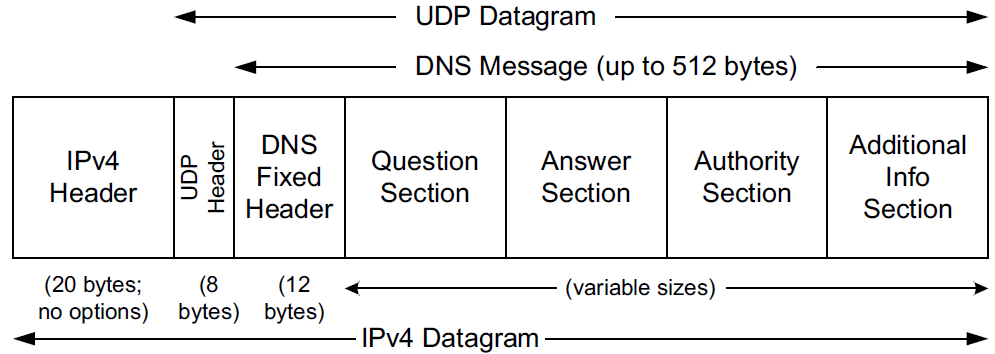
When a resolver issues a query and the response comes back with the TC bit field set ("truncated"), the size of the true response exceeded 512 bytes, so only the first 512 bytes are returned by the server.
-
The resolver may issue the request again, using TCP, which now must be a supported configuration [RFC5966].
-
This allows more than 512 bytes to be returned because TCP breaks up large messages into multiple segments.
When a secondary name server for a zone starts up, it normally performs a zone transfer from the primary name server for the zone.
-
Zone transfers can also be initiated by a timer or as a result of a DNS NOTIFY message.
-
Full zone transfers use TCP as they can be large.
-
Incremental zone transfers, where only the updated entries are transferred, may use UDP at first but switch to TCP if the response is too large, just like a conventional query.
When UDP is used, both the resolver and the server application software must perform their own timeout and retransmission.
-
A recommendation for how to do this is given in [RFC1536].
-
It suggests starting with a timeout of at least 4s, and that subsequent timeouts result in an exponential increase of the timeout (a bit like TCP’s algorithms).
-
Linux and UNIX-like systems allow a change to be made to the retransmission timeout parameters by altering the contents of the /etc/resolv.conf file (by setting the timeout and attempts options).
x@node-0:~$ dig +short +tcp @8.8.8.8 cs.berkeley.edu A
23.185.0.1
x@node-0:~$ sudo tcpdump -tnv \(tcp or udp\) and port 53
IP (tos 0x0, ttl 64, id 30721, offset 0, flags [none], proto TCP (6), length 60)
192.168.91.128.44587 > 8.8.8.8.53: Flags [S], cksum 0xbe79 (correct), seq 1999751284, win 64240, options [mss 1460,sackOK,TS val 3664026097 ecr 0,nop,wscale 7], length 0
IP (tos 0x0, ttl 128, id 5910, offset 0, flags [none], proto TCP (6), length 44)
8.8.8.8.53 > 192.168.91.128.44587: Flags [S.], cksum 0x18e7 (correct), seq 1120675634, ack 1999751285, win 64240, options [mss 1460], length 0
IP (tos 0x0, ttl 64, id 30722, offset 0, flags [none], proto TCP (6), length 40)
192.168.91.128.44587 > 8.8.8.8.53: Flags [.], cksum 0x30a4 (correct), ack 1, win 64240, length 0
IP (tos 0x0, ttl 64, id 30723, offset 0, flags [none], proto TCP (6), length 98)
192.168.91.128.44587 > 8.8.8.8.53: Flags [P.], cksum 0xfd6a (correct), seq 1:59, ack 1, win 64240, length 58 32781+ [1au] A? cs.berkeley.edu. (56)
IP (tos 0x0, ttl 128, id 5911, offset 0, flags [none], proto TCP (6), length 40)
8.8.8.8.53 > 192.168.91.128.44587: Flags [.], cksum 0x306a (correct), ack 59, win 64240, length 0
IP (tos 0x0, ttl 128, id 5912, offset 0, flags [none], proto TCP (6), length 102)
8.8.8.8.53 > 192.168.91.128.44587: Flags [P.], cksum 0x8005 (correct), seq 1:63, ack 59, win 64240, length 62 32781 1/0/1 cs.berkeley.edu. A 23.185.0.1 (60)
IP (tos 0x0, ttl 64, id 30724, offset 0, flags [none], proto TCP (6), length 40)
192.168.91.128.44587 > 8.8.8.8.53: Flags [.], cksum 0x306a (correct), ack 63, win 64178, length 0
IP (tos 0x0, ttl 64, id 30725, offset 0, flags [none], proto TCP (6), length 40)
192.168.91.128.44587 > 8.8.8.8.53: Flags [F.], cksum 0x3069 (correct), seq 59, ack 63, win 64178, length 0
IP (tos 0x0, ttl 128, id 5913, offset 0, flags [none], proto TCP (6), length 40)
8.8.8.8.53 > 192.168.91.128.44587: Flags [.], cksum 0x302c (correct), ack 60, win 64239, length 0
IP (tos 0x0, ttl 128, id 5914, offset 0, flags [none], proto TCP (6), length 40)
8.8.8.8.53 > 192.168.91.128.44587: Flags [FP.], cksum 0x3023 (correct), seq 63, ack 60, win 64239, length 0
IP (tos 0x0, ttl 64, id 0, offset 0, flags [DF], proto TCP (6), length 40)
192.168.91.128.44587 > 8.8.8.8.53: Flags [.], cksum 0x3068 (correct), ack 64, win 64178, length 04.3. Question (Query) and Zone Section Format
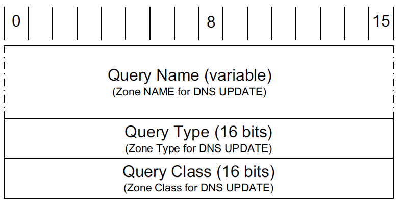
The question or query section of a DNS message lists the question(s) being referenced. The same structure is also used for the zone section in dynamic updates, but with different names.
-
The Query Name is the domain name being looked up, using the encoding for labels.
-
Each question has a Query Type and Query Class.
The class value is 1, 254, or 255, indicating the Internet class, no class, or all classes, respectively, for all cases in which we are interested (other values are not typically used for TCP/IP networks).
The Query Type field holds a value indicating the type of query being performed.
-
The most common query type is A (or AAAA if IPv6 DNS resolution is enabled), which means that an IP address is desired for the query name.
-
It is also possible to create a query of type ANY, which returns all RRs of any type in the same class that match the query name.
-
4.4. Answer, Authority, and Additional Information Section Formats
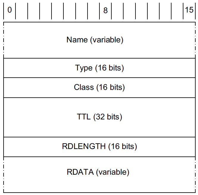
The final three sections in the DNS message, the answer, authority, and additional information sections, contain sets of RRs.
-
The Name field (sometimes called the "owning name", "owner", or "record owner’s name") is the domain name to which the following resource data corresponds.
-
The Type field specifies one of the RR type codes.
-
The Class field is 1 for Internet data.
-
The TTL field is the number of seconds for which the RR can be cached.
-
The Resource Data Length (RDLENGTH) field specifies the number of bytes contained in the Resource Data (RDATA) field.
4.5. Resource Record Types
Although DNS is most commonly used to determine the IP address(es) that correspond to a particular name, it can also be used for the opposite purpose and for a number of other things. The wide range of capabilities provided by DNS is largely attributable to its ability to have different types of resource records.
| Value | RR Type | Reference | Description and Purpose |
|---|---|---|---|
1 |
A |
[RFC1035] |
Address record for IPv4 (32-bit IPv4 address) |
2 |
NS |
[RFC1035] |
Name server; provides name of authoritative name server for zone |
5 |
CNAME |
[RFC1035] |
Canonical name; maps one name to another (to provide a form of name aliasing) |
6 |
SOA |
[RFC1035] |
Start of authority; provides authoritative information for the zone (name servers, e-mail address of contact, serial number, zone transfer timers) |
12 |
PTR |
[RFC1035] |
Pointer; provides address to (canonical) name mapping; used with in-addr.arpa and ip6.arpa domains for IPv4 and IPv6 reverse queries |
15 |
MX |
[RFC1035] |
Mail exchanger; provides name of e-mail handling host for a domain |
16 |
TXT |
[RFC1035] [RFC1464] |
Text; provides a variety of information (e.g., used with SPF anti-spam scheme to identify authorized e-mail servers) |
28 |
AAAA |
[RFC3596] |
Address record for IPv6 (128-bit IPv6 address) |
33 |
SRV |
[RFC2782] |
Server selection; transport endpoints of a generic service |
35 |
NAPTR |
[RFC3403] |
Name authority pointer; supports alternative name spaces |
41 |
OPT |
[RFC2671] |
Pseudo-RR; supports larger datagrams, labels, return codes in EDNS0 |
251 |
IXFR |
[RFC1995] |
Incremental zone transfer |
252 |
AXFR |
[RFC1035] [RFC5936] |
Full zone transfer; carried over TCP |
255 |
(ANY) |
[RFC1035] |
Request for all (any) records |
Resource records are used for many purposes but can be divided into three broad categories: data types, query types, and meta types.
-
Data types are used to convey information stored in the DNS such as IP addresses and the names of authoritative name servers.
-
Query types use the same values as data types, with a few additional values (e.g., AXFR, IXFR, and *).
-
Meta types designate transient data associated with a particular single DNS message.
4.5.1. Authority (SOA) Records
In DNS, each zone has an authority record, using an RR type called start of authority (SOA). These records provide authoritative links between portions of the DNS name space and the servers that provide the zone information allowing various queries to be performed for addresses and other information.
The SOA RR is used to identify the name of the host providing the official permanent database,
-
the responsible party’s e-mail address (where "." is used instead of @),
-
zone update parameters,
-
and the default TTL.
The default TTL is applied to RRs in the zone that are not otherwise assigned an explicit per-RR TTL.
The zone update parameters include a serial number, refresh time, retry time, and expire time.
-
The serial number is increased (by at least 1), usually by the network administrator, anytime there is a change to the zone contents.
It is used by secondary servers to determine if they should initiate a zone transfer (when they do not have a copy of the zone contents with largest serial number).
-
The refresh time tells secondary servers how long to wait before checking the SOA record from the primary and its version number to determine if a zone transfer is required.
-
The retry and expire times are used in the case of zone transfer failure.
The retry value gives the time (in seconds) a secondary will wait before retrying.
The expire time is an upper bound (in seconds) that a secondary server will keep retrying zone transfers before giving up. If it gives up, such a server ceases to respond to queries for the zone.
In general, a zone can contain a mix of IPv4 and IPv6 data and can be accessed using either version of IP.
$ nslookup
> set type=soa
> codefarm.me
Server:		192.168.91.2
Address:	192.168.91.2#53

Non-authoritative answer:
codefarm.me
	origin = ns01.domaincontrol.com
	mail addr = dns.jomax.net
	serial = 2023020900
	refresh = 28800
	retry = 7200
	expire = 604800
	minimum = 600

Authoritative answers can be found from:
> exit
4.5.2. Mail Exchanger (MX) Records
An MX record provides the name of a mail exchanger—a host willing to engage in the Simple Mail Transfer Protocol (SMTP) [RFC5321] to receive incoming e-mail on behalf of users associated with a domain name.
MX records include a preference value, so that more than one MX record may be present for a particular domain name, which allows a sending agent to sort the hosts in preference order (smaller is more preferable) in deciding which host to use as an e-mail destination.
x@node-0:~$ nslookup
> set type=mx
> server ns3.dns.ucla.edu
Default server: ns3.dns.ucla.edu
Address: 54.236.209.157#53
Default server: ns3.dns.ucla.edu
Address: 2600:1f18:21d4:e000::53#53
> cs.ucla.edu
Server:		ns3.dns.ucla.edu
Address:	54.236.209.157#53

CS.UCLA.EDU	mail exchanger = 13 Mailman.CS.UCLA.EDU.
CS.UCLA.EDU	mail exchanger = 3 Pelican.CS.UCLA.EDU.
4.5.3. Fighting Spam: The Sender Policy Framework (SPF) and Text (TXT) Records
For outgoing e-mail, MX records allow the DNS to help determine the names of mail relays and servers for a domain. More recently, the DNS has been leveraged by receiving mail agents to determine which relaying or sending mail servers are authorized to send mail from a particular domain name. This is used to help combat spam (unwanted e-mail) that is sent by a rogue mail agent pretending to be an authorized mail sender.
E-mail received by a mail server is rejected, stored, or forwarded to another mail server.
-
Rejection can happen for a number of reasons, such as a protocol error or lack of available storage space at the receiver.
-
It can also be rejected because the sending mail client does not appear to be the proper one for sending e-mail.
This capability is supported by the Sender Policy Framework (SPF) and documented in [RFC4408], an experimental RFC.
There is another framework known as Sender ID [RFC4406] that incorporates SPF’s functions. It is also experimental but less widely deployed.
Version 1 of SPF uses DNS TXT or SPF (type 99) resource records.
-
Records are set up and published in the DNS by a domain’s owner to indicate which servers are authorized to send mail originating from the domain.
-
The text contains the matching criteria (called mechanisms) and other information (called modifiers).
-
Preceding each mechanism is a qualifier that determines the consequence of a matching mechanism.
Any mechanism missing a qualifier is assumed to have the + qualifier.
-
The
+qualifier indicates that a match results in a Pass indication. -
Other possible qualifiers include
-(Fail),~(Soft Fail), and?(Neutral).
If none of the matching mechanisms produces a Pass result, the final mechanism (all) matches any condition.
-
The tilde character (
~) before the all criterion indicates that a Soft Fail return should be generated if all is the only matching mechanism.The exact way a soft failure is handled is dependent on the receiving e-mail software.
x@node-0:~$ dig +tcp +nocmd +nostats txt outlook.com
;; Got answer:
;; ->>HEADER<<- opcode: QUERY, status: NOERROR, id: 18595
;; flags: qr rd ra; QUERY: 1, ANSWER: 3, AUTHORITY: 0, ADDITIONAL: 1

;; OPT PSEUDOSECTION:
; EDNS: version: 0, flags:; udp: 4000
;; QUESTION SECTION:
;outlook.com.			IN	TXT

;; ANSWER SECTION:
outlook.com.		349	IN	TXT	"v=spf1 include:spf-a.outlook.com include:spf-b.outlook.com ip4:157.55.9.128/25 include:spf.protection.outlook.com include:spf-a.hotmail.com include:_spf-ssg-b.microsoft.com include:_spf-ssg-c.microsoft.com ~all"
outlook.com.		349	IN	TXT	"google-site-verification=0iLWhIMhXEkeWwWfFU4ursTn-_OvoOjaA0Lr7Pg1sEM"
outlook.com.		349	IN	TXT	"google-site-verification=DC2uC-T8kD33lINhNzfo0bNBrw-vrCXs5BPF5BXY56g"

x@node-0:~$ dig +tcp +nocmd +nostats txt spf-a.outlook.com
;; Got answer:
;; ->>HEADER<<- opcode: QUERY, status: NOERROR, id: 1423
;; flags: qr rd ra; QUERY: 1, ANSWER: 1, AUTHORITY: 0, ADDITIONAL: 1

;; OPT PSEUDOSECTION:
; EDNS: version: 0, flags:; udp: 4000
;; QUESTION SECTION:
;spf-a.outlook.com.		IN	TXT

;; ANSWER SECTION:
spf-a.outlook.com.	380	IN	TXT	"v=spf1 ip4:157.56.232.0/21 ip4:157.56.240.0/20 ip4:207.46.198.0/25 ip4:207.46.4.128/25 ip4:157.56.24.0/25 ip4:157.55.157.128/25 ip4:157.55.61.0/24 ip4:157.55.49.0/25 ip4:65.55.174.0/25 ip4:65.55.126.0/25 ip4:65.55.113.64/26 ip4:65.55.94.0/25 -all"
Reading from left to right in the above example,
-
the string
v=spf1is a modifier indicating that the SPF version is 1. -
The
ip4mechanism specifies that the SMTP sender has an IPv4 address with the prefix. -
The
ip6mechanism specifies any sending host with IPv6 address prefix. -
Finally, the
includemechanism incorporates, by reference, the TXT records with recursive SPF resource records.
4.6. Zone Transfers and DNS NOTIFY
A zone transfer is used to copy a set of RRs for a zone from one server to another (generally from the master server to slave servers). The purpose of doing so is to keep multiple servers in sync with respect to a zone’s contents.
-
Multiple servers provide resiliency to failure, in case a server should go down.
-
Performance can also be improved as multiple servers can be used to share the processing load for incoming queries.
-
Finally, the latency of a DNS query/response can potentially be reduced if servers are placed in locations close to clients (i.e., where the network latency between resolver and server is small).
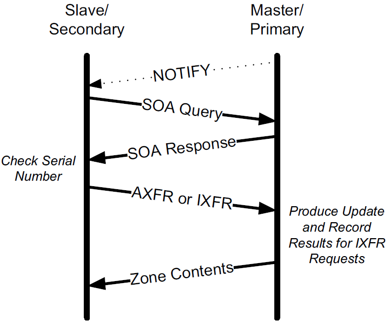
As originally specified, zone transfers are initiated after polling, where slaves periodically contact masters to see if a zone transfer is necessary by comparing the zones' version numbers.
A later method says if a zone transfer needs to be initiated using an asynchronous update mechanism when the zone contents change, called DNS NOTIFY.
Once a zone transfer is initiated, either the entire zone is transferred (using DNS AXFR messages) [RFC5936], or an incremental zone transfer option may be used (using DNS IXFR messages) [RFC1995].
5. Sort Lists, Round-Robin, and Split DNS
A DNS server could return all matching data to any client in whatever order the server finds most convenient.
However, special configuration options and behaviors are available in most DNS server software to achieve certain operational, privacy, or performance goals.
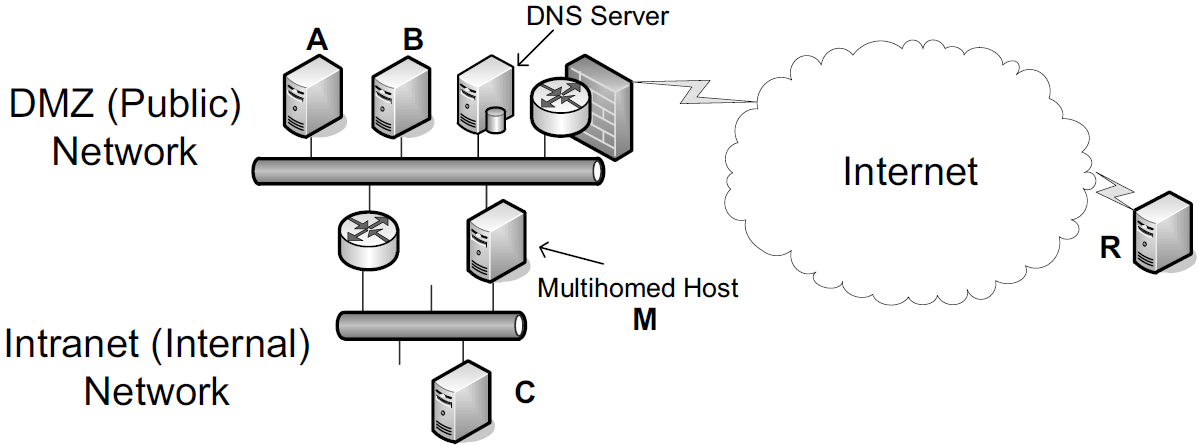
A host wishing to contact M performs a DNS lookup that returns two addresses—one associated with the internal network and one with the DMZ.
Naturally, it would be more efficient if A, B, and R reached M via the DMZ and C reached M via the internal network.
-
This generally happens if the DNS server orders its returned address records based on the source IP address of the request.
-
It could also use the destination IP address, especially if M uses multiple IP addresses from different subnets on the same network interface.
To achieve load balancing, the DNS server may be configured to use DNS round-robin, which means that the server permutes the order of the returned address records. While this helps to balance load, it is far from perfect.
-
When records are cached, the desired effect may not occur because of reuse of existing cached address records.
-
In addition, this scheme may balance the number of connections well across servers, but not the load.
Different connections can have radically different processing requirements, so the true processing load is likely to remain unbalanced unless the particular service always has the same processing requirements.
In split DNS, the set of resource records returned in response to a query is dependent on the identity of the client and possibly query destination address. With split DNS, we could arrange for
-
any host in the enterprise (i.e., those sharing a set of prefixes) to be provided with the entire DNS database,
-
whereas those outside are given visibility only to A and B, where the main Web service is offered.
6. Open DNS Servers and DynDNS
Many home users are assigned a single IPv4 address by their ISP, and this address may change over time as the user’s computer or home gateway connects, disconnects, and reconnects to the Internet.
Consequently, it is often difficult for the user to establish a DNS entry that allows for running services that are visible from the Internet.
A number of so-called open Dynamic DNS (DDNS) servers are available that support a special update protocol called the DNS Update API, whereby a user may update an entry in a provider’s DNS server given a preregistration or account.
7. LLMNR and mDNS
The ordinary DNS system requires a set of DNS servers to be configured to provide mappings between names and addresses, and possibly other information.
Sometimes this is too much overhead when only a few local hosts wish to communicate.
In cases where a DNS server is not available (e.g., a quickly formed ad hoc network of clients that connect only to each other), a special local version of DNS called Link-Local Multicast Name Resolution (LLMRR) [RFC4795] may be available.
-
It is a (nonstandard) protocol based on DNS developed by Microsoft and used in local environments to help discover devices on a local area network, such as printers and file servers.
-
It is supported in Windows Vista, Server 2008, and 7.
-
It uses UDP port 5355 with the IPv4 multicast address 224.0.0.252 and IPv6 address ff02::1:3.
-
The servers also use TCP on port 5355 from whatever unicast IP address they respond from.
Multicast DNS (mDNS) [IDMDNS] is another form of local DNS-like capability developed by Apple.
-
When it is combined with the DNS Service Discovery protocol, Apple calls the resulting framework Bonjour.
-
mDNS uses DNS messages carried over local multicast addresses.
-
It uses UDP with port 5353.
-
It specifies that the special TLD .local is to be treated with special semantics. The .local TLD is link-local in scope.
-
Any DNS queries for domain names in this TLD are sent to the mDNS IPv4 address 224.0.0.251 or the IPv6 address ff02::fb.
-
Queries for other domains may optionally be sent to these multicast addresses.
-
x@node-0:~$ systemctl status avahi-daemon.service
● avahi-daemon.service - Avahi mDNS/DNS-SD Stack
     Loaded: loaded (/lib/systemd/system/avahi-daemon.service; enabled; vendor preset: enabled)
     Active: active (running) since Wed 2022-12-14 11:53:34 CST; 5min ago
TriggeredBy: ● avahi-daemon.socket
   Main PID: 1864 (avahi-daemon)
     Status: "avahi-daemon 0.8 starting up."
      Tasks: 2 (limit: 4633)
     Memory: 784.0K
        CPU: 23ms
     CGroup: /system.slice/avahi-daemon.service
             ├─1864 avahi-daemon: running [node-0.local]
             └─1865 avahi-daemon: chroot helper

x@node-0:~$ sudo systemctl restart avahi-daemon.service

x@node-0:~$ cat /etc/resolv.conf
domain localdomain
search localdomain
nameserver 192.168.91.2

x@node-0:~$ ping -c 1 node-1
PING node-1.localdomain (192.168.91.137) 56(84) bytes of data.
64 bytes from 192.168.91.137 (192.168.91.137): icmp_seq=1 ttl=64 time=0.216 ms

--- node-1.localdomain ping statistics ---
1 packets transmitted, 1 received, 0% packet loss, time 0ms
rtt min/avg/max/mdev = 0.216/0.216/0.216/0.000 ms
x@node-0:~$ sudo tcpdump -tnv port 53 or port 5353
tcpdump: listening on ens32, link-type EN10MB (Ethernet), snapshot length 262144 bytes
IP (tos 0x0, ttl 64, id 22416, offset 0, flags [DF], proto UDP (17), length 64)
192.168.91.128.57800 > 192.168.91.2.53: 43159+ A? node-1.localdomain. (36)
IP (tos 0x0, ttl 64, id 22417, offset 0, flags [DF], proto UDP (17), length 64)
192.168.91.128.57800 > 192.168.91.2.53: 16776+ AAAA? node-1.localdomain. (36)
IP (tos 0x0, ttl 128, id 17525, offset 0, flags [none], proto UDP (17), length 136)
192.168.91.2.53 > 192.168.91.128.57800: 16776 NXDomain 0/1/0 (108)
IP (tos 0x0, ttl 1, id 50969, offset 0, flags [none], proto UDP (17), length 58)
192.168.91.1.5353 > 224.0.0.251.5353: 0 A (QM)? node-1.local. (30)
IP (tos 0x0, ttl 255, id 5793, offset 0, flags [DF], proto UDP (17), length 84)
192.168.91.137.5353 > 224.0.0.251.5353: 0*- [0q] 2/0/0 node-1.local. (Cache flush) A 192.168.91.137, node-1.local. (Cache flush) A 192.168.91.135 (56)
IP6 (flowlabel 0xfc266, hlim 1, next-header UDP (17) payload length: 38) fe80::50c2:d6ef:87fb:1b7b.5353 > ff02::fb.5353: [udp sum ok] 0 A (QM)? node-1.local. (30)
IP (tos 0x0, ttl 128, id 17526, offset 0, flags [none], proto UDP (17), length 80)
192.168.91.2.53 > 192.168.91.128.57800: 43159*- 1/0/0 node-1.localdomain. A 192.168.91.137 (52)x@node-0:~$ ss -lun
State Recv-Q Send-Q Local Address:Port Peer Address:Port Process
UNCONN 0 0 0.0.0.0:36812 0.0.0.0:*
UNCONN 0 0 0.0.0.0:68 0.0.0.0:*
UNCONN 0 0 0.0.0.0:5353 0.0.0.0:*
UNCONN 0 0 [::]:42022 [::]:*
UNCONN 0 0 [::]:5353 [::]:*
x@node-0:~$ sudo ip m
1: lo
inet 224.0.0.251
inet 224.0.0.1
inet6 ff02::fb
inet6 ff02::1
inet6 ff01::1
2: ens32
link 01:00:5e:00:00:01
link 01:00:5e:00:00:fb
link 33:33:00:00:00:01
link 33:33:ff:60:32:80
link 33:33:00:00:00:fb
inet 224.0.0.251
inet 224.0.0.1
inet6 ff02::fb
inet6 ff02::1:ff60:3280
inet6 ff02::1
inet6 ff01::1