Understanding the Linux Kernel 02
对枯燥的事情有所坚持—耗子
2.1 Memory Addresses
Programmers casually refer to a memory address as the way to access the contents of a memory cell. But when dealing with Intel 80x86 microprocessors, we have to distinguish among three kinds of addresses:
-
Logical address
Included in the machine language instructions to specify the address of an operand or of an instruction. This type of address embodies the well-known Intel segmented architecture that forces MS-DOS and Windows programmers to divide their programs into segments. Each logical address consists a segment and an offset (or displacement) that denotes the distance from the start of the segment to the actual address.
-
Linear address
A single 32-bit unsigned integer that can be used to address up 4 GB, that is, up to 4,294,967,296 memory cells. Linear addresses are usually represented in hexadecimal notation; their values range from 0x00000000 to 0xffffffff.
-
Physical address
Used to address memory cells included in memory chips. They correspond to the electrical signals sent along the address pins of the microprocessor to the memory bus. Physical addresses are represented as 32-bit unsigned integers.
The CPU control unit transforms a logical address into a linear address by means of a hardware circuit called a segmentation unit; successively, a second hardware circuit called a paging unit transforms the linear address into a physical address.

2.2 Segmentation in Hardware
Starting with the 80386 model, Intel microprocessors perform address translation in two different ways called real mode and protected mode. Real mode exists mostly to maintain processor compatibility with older models and to allow the operating system to bootstrap.
2.2.1 Segmentation Registers
A logical address consists of two parts: a segment identifier and an offset that specifies the relative address within the segment. The segment identifier is a 16-bit field called Segment Selector, while the offset is a 32-bit field.
To make it easy to retrieve segment selectors quickly, the processor provides segmentation registers whose only purpose is to hold Segment Selectors: these registers are called cs, ss, ds, es, fs and gs. Although there are only six of them, a program can reuse the same segmentation register for different purposes by saving its content in memory and then restoring it later.
Three of the six segmentation registers have specific purposes:
-
cs
The code segment register, which points to a segment containing program instructions
-
ss
The stack segment register, which points to a segment containing the current progam stack
-
ds
The data segment register, which points to a segment containing static and external data
The remaining three segmentation registers are general purpose and may refer to arbitrary segments.
The cs register has another important function: it includes a 2-bit field that specifies the Current Privilege Level (CPL) of the CPU. The value 0 denotes the highest privilege level, while the value 3 denotes the lowest one. Linux uses only levels 0 and 3, which are respectively called Kernel Mode and User Mode.
2.2.2 Segment Descriptors
Each segment is represented by an 8-byte Segment Descriptor that describes the segment characteristics. Segment Descriptors are stored either in the Global Descriptor Table(GDT) or in the Local Descriptor Table(LDT).
Usually only one GDT is defined, while each process have its onw LDT. The address of the GDT in main memory is contained in the gdtr processor register and the address of the currently used LDT is contained in the ldtr processor register.
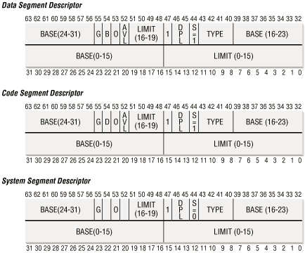
Each Segment Descriptor consists of the following fields:
-
A 32-bit Base field contains the linear address of the first byte of the segment.
- A G grannularity flag: if it is cleared, the segment size is expressed in bytes; otherwise, it is expressed in multiples of 4096 bytes.
- A 20-bit Limit field that denotes the segment length in bytes. If G is set to 0, the size of a non-null segment may vary between 1 byte and 1 MB; otherwise, it may vary between 4KB and 4 GB.
- An S system flag: if it is cleared, the segment is a system segment that stores kernel data structures; otherwise, it is a normal code or data segment.
-
A 4-bit Type field that characterize the segment type and its access rights. The following Segment Descriptor type are widely used:
-
Code Segment Descritpor
Indicates that the Segment Descriptor refers to a code segment; it may be included either in the GDT or in the LDT. The descriptor has the S flag set.
-
Data Segment Decriptor
Indicates that the Segment Descriptor refers to a data segment; it may be included either in the GDT or in the LDT. The descriptor has the S flag set. Stack segments are implemented by means of generic data segment.
-
Task State Segment Descriptor (TSSD)
Indicates that the Segment Descriptor refers to a Task State Segment (TSS), that is, a segment used to save the contents of the processor registers, it can apear only in the GDT. The corresponding Type field has the value 11 or 9, depending on whether the corresponding process is currently executing on the CPU. The S flag of such descriptors is set to 0.
-
Local Descritpor Table Descritpor (LDTD)
Indicates that the Segment Descriptor refers to a segment containing an LDT; it can apear only in the GDT. The corresponding Type field has the value 2. The S flag of such descriptors is set to 0.
-
- A DPL (Descriptor Privilege Level) 2-bit field used to restrict accesses to the segment. It represent the minimal CPU privilege level requested for accessing the segment. Therefore, a segment with it DPL set to 0 is accssible only when the CPL is 0, that is, in Kernel Mode, while a segment with its DPL set to 3 is accessible with every CPL value.
- A Segment-Present flag that is set to if the segment is currently not stored in main memory. Linux always set this filed to 1, since it never swaps out whole segments to disk.
- An additional flag called D or B depending on whether the segment contains code or data. Its meaning is slightly different in the two cases, but it is basically set if the address used as segment offsets are 32 bits long and it is cleared if they are 16 bits long.
- A reseved bit (bit 53) always set to 0.
- An AVL flag that may be used by the operating system but is ignored in Linux.
References
- Daniel P. Bovet、 Marco Cesati (2005-11), “Chapter 2: Understanding the Linux Kernel”
- Real mode - Wikipedia, https://en.wikipedia.org/wiki/Real_mode
- Protected mode - Wikipedia, https://en.wikipedia.org/wiki/Protected_mode
- Difference between real mode and protected mode - Geek.com, https://www.geek.com/chips/difference-between-real-mode-and-protected-mode-574665/
- Memory segmentation - Wikipedia, https://en.wikipedia.org/wiki/Memory_segmentation
- x86 memory segmentation - Wikipedia, https://en.wikipedia.org/wiki/X86_memory_segmentation
- x86 assembly language - Wikipedia, https://en.wikipedia.org/wiki/X86_assembly_language