Network Router, Switch, Bridge and Hub
1. Forwarding information base
A forwarding information base (FIB), also known as a forwarding table or MAC table, is most commonly used in network bridging, routing, and similar functions to find the proper output network interface to which the input interface should forward a packet. It is a dynamic table that maps MAC addresses to ports. It is the essential mechanism that separates network switches from Ethernet hubs. Content-addressable memory (CAM) is typically used to efficiently implement the FIB, thus it is sometimes called a CAM table.
2. Routing information base
In computer networking, a routine table, or routing information base (RIB), is a data table stored in a router or a network host that lists the routes to particular network destinations, and in some cases, metrics (distances) associated with those routes. The routing table contains information about the topology of the network immediately around it.
The construction of routing tables is the primary goal of routing protocols. Static routes are entries made in a routing table by non-automatic means and which are fixed rather than being the result of routing protocols and associated network topology-discovery procedures.
3. IP routing
IP routing is the field of routing methodologies of Internet Protocol (IP) packets within and across IP networks. This involves not only protocols and technologies but includes the policies of the worldwide organization and configuration of Internet infrastructure. In each IP network node, IP routing involves the determination of a suitable path for a network packet from a source to its destination in an IP network. The process uses static configuration rules or dynamically obtained status information to select specific packet forwarding methods to direct traffic to the next available intermediate network node one hop closer to the desired final destination, a total path potentially spanning multiple computer networks.
Networks are separated from each other by specialized hosts, called gateways or routers with specialized software support optimized for routing. In routers, packets arriving at an interface are examined for source and destination addressing and queued to the appropriate outgoing interface according to their destination address and a set of rules and performance metrics. Rules are encoded in a routing table that contains entries for all interfaces and their connected networks. If no rule satisfies the requirements for a network packet, it is forwarded to a default route. Routing tables are maintained either manually by a network administrator, or updated dynamically with a routing protocol. Routing rules may contain other parameters than source and destination, such as limitations on available bandwidth, expected packet loss rates, and specific technology requirements.
IP forwarding algorithms take into account the size of each packet, the type of service specified in the header, as well as characteristics of the available links to other routers in the network, such as link capacity, utilization rate, and maximum datagram size that is supported on the link. In general, most routing software determines a route through a shortest path algorithm. However, other routing protocols may use other metrics for determining the best path. Based on the metrics required and present for each link, each path has an associated cost. The routing algorithm attempts to minimize the cost when choosing the next hop.
A routing protocol is a software mechanism by which routers communicate and share information about the topology of the network, and the capabilities of each routing node. It thus implements the network-global rules by which traffic is directed within a network and across multiple networks. Different protocols are often used for different topologies or different application areas. For example, the Open Shortest Path First (OSPF) protocol is generally used for routing packets between subnetworks within an enterprise and the Border Gateway Protocol (BGP) is used on a global scale. BGP is the de facto standard of worldwide Internet routing.
3.1. IP address and CIDR
An Internet Protocol address (IP address) is a numerical label such as 192.0.2.1 that is connected to a computer network that uses the Internet Protocol for communication. An IP address serves two main functions: host or network interface identification and location addressing.
IP addresses are written and displayed in human-readable notations, such as 192.0.2.1 in IPv4, and 2001:db8:0:1234:0:567:8:1 in IPv6. The size of the routing prefix of the address is designated in CIDR notation by suffixing the address with the number of significant bits, e.g., 192.0.2.1/24, which is equivalent to the historically used subnet mask 255.255.255.0.
3.1.1. Subnetworks
IP networks may be divided into subnetworks in both IPv4 and IPv6. For this purpose, an IP address is recognized as consisting of two parts: the network prefix in the high-order bits and the remaining bits called the rest field, host identifier, or interface identifier (IPv6), used for host numbering within a network. The subnet mask or CIDR notation determines how the IP address is divided into network and host parts.
The term subnet mask is only used within IPv4. Both IP versions however use the CIDR concept and notation. In this, the IP address is followed by a slash and the number (in decimal) of bits used for the network part, also called the routing prefix. For example, an IPv4 address and its subnet mask may be 192.0.2.1 and 255.255.255.0, respectively. The CIDR notation for the same IP address and subnet is 192.0.2.1/24, because the first 24 bits of the IP address indicate the network and subnet.
3.1.2. IPv4 addresses
| Class | Leading bits | Size of network number bit field | Size of rest bit field | Start address | End address |
|---|---|---|---|---|---|
A |
0 |
8 |
24 |
0.0.0.0 |
127.255.255.255 |
B |
10 |
16 |
16 |
128.0.0.0 |
191.255.255.255 |
C |
110 |
24 |
8 |
192.0.0.0 |
223.255.255.255 |
| Name | CIDR block | Address range | Classful description |
|---|---|---|---|
24-bit block |
10.0.0.0/8 |
10.0.0.0 – 10.255.255.255 |
Single Class A. |
20-bit block |
172.16.0.0/12 |
172.16.0.0 – 172.31.255.255 |
Contiguous range of 16 Class B blocks. |
16-bit block |
192.168.0.0/16 |
192.168.0.0 – 192.168.255.255 |
Contiguous range of 256 Class C blocks. |
3.1.3. IPv6 addresses
IPv6 addresses have 128 bits. The 128 bits of an IPv6 address are represented in 8 groups of 16 bits each. Each group is written as four hexadecimal digits and the groups are separated by colons (:). An example of this representation is 2001:0db8:0000:0000:0000:ff00:0042:8329.
For convenience and clarity, the representation of an IPv6 address may be shortened with the following rules.
-
One or more leading zeros from any group of hexadecimal digits are removed, which is usually done to all of the leading zeros. For example, the group 0042 is converted to 42.
-
Consecutive sections of zeros are replaced with two colons (::). This may only be used once in an address, as multiple use would render the address indeterminate. RFC 5952 requires that a double colon not be used to denote an omitted single section of zeros.
An example of application of these rules:
-
Initial address: 2001:0db8:0000:0000:0000:ff00:0042:8329.
-
After removing all leading zeros in each group: 2001:db8:0:0:0:ff00:42:8329.
-
After omitting consecutive sections of zeros: 2001:db8::ff00:42:8329.
The loopback address 0000:0000:0000:0000:0000:0000:0000:0001 is defined in RFC 5156 and is abbreviated to ::1 by using both rules.
As an IPv6 address may have more than one representation, the IETF has issued a proposed standard for representing them in text.
Because IPv6 addresses contain colons, and URLs use colons to separate the host from the port number, RFC2732 specifies that an IPv6 address used as the host-part of a URL should be enclosed in square brackets, e.g. http://[2001:db8:4006:812::200e] or http://[2001:db8:4006:812::200e]:8080/path/page.html.
3.1.4. Classless Inter-Domain Routing
Classless Inter-Domain Routing (CIDR /ˈsaɪdər, ˈsɪ-/) is a method for allocating IP addresses and for IP routing. The Internet Engineering Task Force introduced CIDR in 1993 to replace the previous classful network addressing architecture on the Internet. Its goal was to slow the growth of routing tables on routers across the Internet, and to help slow the rapid exhaustion of IPv4 addresses.
CIDR encompasses several concepts. It is based on variable-length subnet masking (VLSM) which allows the specification of arbitrary-length prefixes. CIDR introduced a new method of representation for IP addresses, now commonly known as CIDR notation, in which an address or routing prefix is written with a suffix indicating the number of bits of the prefix, such as 192.0.2.0/24 for IPv4, and 2001:db8::/32 for IPv6. CIDR introduced an administrative process of allocating address blocks to organizations based on their actual and short-term projected needs. The aggregation of multiple contiguous prefixes resulted in supernets in the larger Internet, which whenever possible are advertised as aggregates, thus reducing the number of entries in the global routing table.
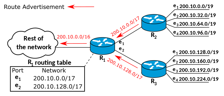
3.1.5. Supernetwork
A supernetwork, or supernet, is an Internet Protocol (IP) network that is formed by combination of multiple networks (or subnets) into a larger network. The new routing prefix for the combined network represents the constituent networks in a single routing table entry. The process of forming a supernet is called supernetting, prefix aggregation, route aggregation, or route summarization.
The benefits of supernetting are conservation of address space and efficiencies gained in routers in terms of memory storage of route information and processing overhead when matching routes. Supernetting, however, can introduce interoperability issues and other risks.
Supernetting requires the use of routing protocols that support Classless Inter-Domain Routing (CIDR). Interior Gateway Routing Protocol, Exterior Gateway Protocol and version 1 of the Routing Information Protocol (RIPv1) assume classful addressing, and therefore cannot transmit the subnet mask information required for supernetting.
Enhanced Interior Gateway Routing Protocol (EIGRP) is a classless routing protocol supporting CIDR. By default, EIGRP summarizes the routes within the routing table and forwards these summarized routes to its peers. This may have an adverse impact in heterogeneous routing environments with discontiguous subnets.
Other routing protocols with CIDR support include RIPv2, Open Shortest Path First, EIGRP, IS-IS and Border Gateway Protocol.
3.2. Routing algorithm
The IP forwarding algorithm is a specific implementation of routing for IP networks. In order to achieve a successful transfer of data, the algorithm uses a routing table to select a next-hop router as the next destination for a datagram. The IP address of the selected router is known as the next-hop address.
When several destinations are matching, the route with the longest subnet mask is chosen (the most specific one). If there are multiple routes with the same subnet mask, the route with the lowest metric is used. If there are multiple default routes, the metric is also used to determine which to use. If there are multiple routes with the same subnet mask and metric, the system may use equal-cost multi-path routing as a forwarding strategy.
When no route is available, an ICMP error message is sent to the originator of the packet, to inform that host that the packet could not be delivered, and to avoid unnecessary retransmission to avoid network congestion. The sending host should either stop transmitting or choose another address or route.
3.3. Routing table
The following presents a typical routing table in a Unix-like operating system:
Kernel IP routing table
Destination     Gateway         Genmask         Flags Metric Ref    Use Iface
0.0.0.0         71.46.14.1      0.0.0.0         UG    0      0        0 ppp0
10.0.0.0        0.0.0.0         255.0.0.0       U     0      0        0 eth0
71.46.14.1      0.0.0.0         255.255.255.255 UH    0      0        0 ppp0
169.254.0.0     0.0.0.0         255.255.0.0     U     0      0        0 eth0
172.16.0.0      0.0.0.0         255.240.0.0     U     0      0        0 eth0
192.168.0.0     0.0.0.0         255.255.0.0     U     0      0        0 eth0
192.168.1.0     192.168.96.1    255.255.255.0   UG    0      0        0 eth0
192.168.96.0    0.0.0.0         255.255.255.0   U     0      0        0 eth0
The host has several network interfaces. eth0 is the interface name of the network interface card representing an Ethernet port. ppp0 is a PPPoE interface, which is configured as the default route in this example.
A default route is recognized by the destination 0.0.0.0 and the flag G. A network router is identified by the network mask 255.255.255.255 and the flag H.
| Flag | Description |
|---|---|
G |
Use Gateway (gateway filled in) |
H |
Target is a Host (bitmask of 32 bits) |
U |
Route is Up |
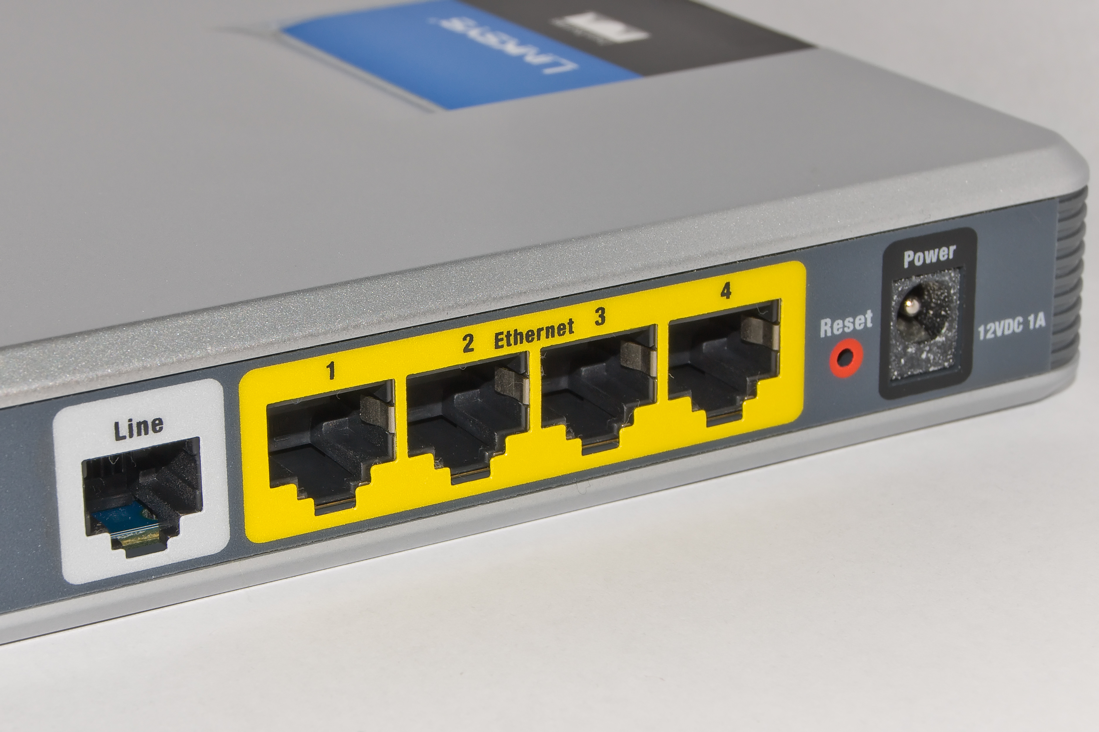
4. Router
A router is a networking device that forwards data packets between computer networks. Routers perform the traffic directing functions on the Internet. Data sent through the internet, such as a web page or email, is in the form of data packets. A packet is typically forwarded from one router to another router through the networks that constitute an internetwork (e.g. the Internet) until it reaches its destination node.
A router is connected to two or more data lines from different IP networks. When a data packet comes in on one of the lines, the router reads the network address information in the packet header to determine the ultimate destination. Then, using information in its routing table or routing policy, it directs the packet to the next network on its journey.
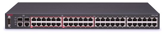
5. Network switch
A network switch (also called switching hub, bridging hub, and, by the IEEE, MAC bridge) is networking hardware that connects devices on a computer network by using packet switching to receive and forward data to the destination device.
A network switch is a multiport network bridge that uses MAC addresses to forward data at the data link layer (layer 2) of the OSI model. Some switches can also forward data at the network layer (layer 3) by additionally incorporating routing functionality. Such switches are commonly known as layer-3 switches or multilayer switches.
Switches for Ethernet are the most common form of network switch. The first Ethernet switch was introduced by Kalpana in 1990.[3] Switches also exist for other types of networks including Fibre Channel, Asynchronous Transfer Mode, and InfiniBand.
Unlike repeater hubs, which broadcast the same data out of each port and let the devices pick out the data addressed to them, a network switch learns the identities of connected devices and then only forwards data to the port connected to the device to which it is addressed.
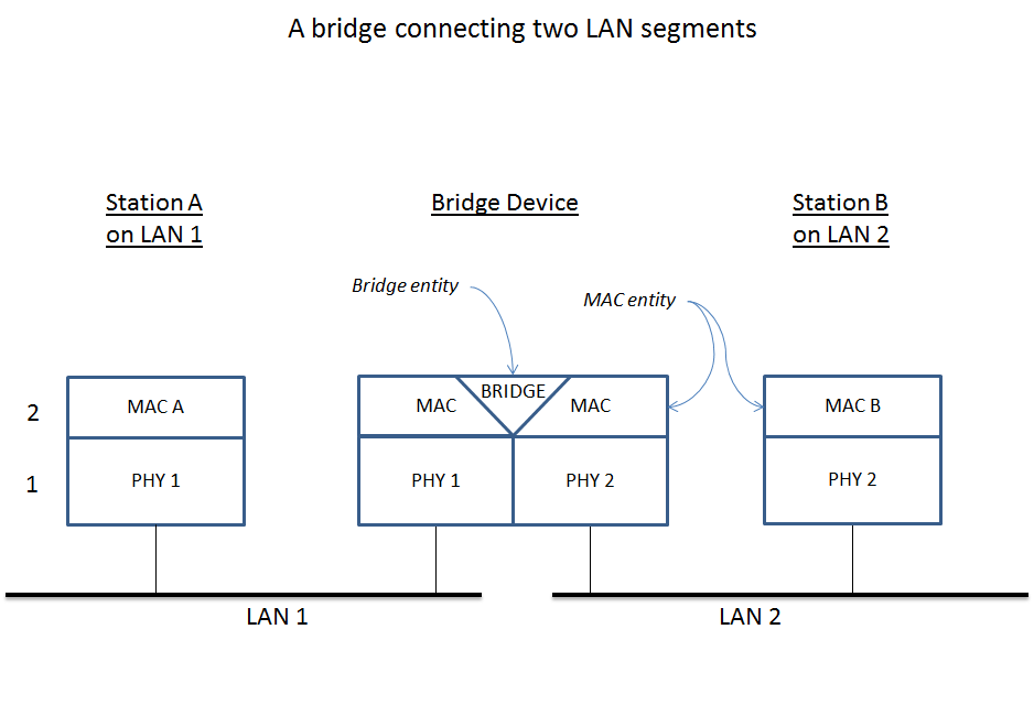
6. Bridging
A network bridge is a computer networking device that creates a single, aggregate network from multiple communication networks or network segments. This function is called network bridging. Bridging is distinct from routing. Routing allows multiple networks to communicate independently and yet remain separate, whereas bridging connects two separate networks as if they were a single network. In the OSI model, bridging is performed in the data link layer (layer 2). If one or more segments of the bridged network are wireless, the device is known as a wireless bridge.
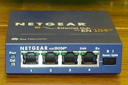
7. Ethernet hub
An Ethernet hub, active hub, network hub, repeater hub, multiport repeater, or simply hub is a network hardware device for connecting multiple Ethernet devices together and making them act as a single network segment. It has multiple input/output (I/O) ports, in which a signal introduced at the input of any port appears at the output of every port except the original incoming. A hub works at the physical layer (layer 1) of the OSI model. A repeater hub also participates in collision detection, forwarding a jam signal to all ports if it detects a collision. In addition to standard 8P8C ("RJ45") ports, some hubs may also come with a BNC or an Attachment Unit Interface (AUI) connector to allow connection to legacy 10BASE2 or 10BASE5 network segments.
Hubs are now largely obsolete, having been replaced by network switches except in very old installations or specialized applications. As of 2011, connecting network segments by repeaters or hubs is deprecated by IEEE 802.3.
8. Network interface controller
A network interface controller (NIC, also known as a network interface card, network adapter, LAN adapter or physical network interface, and by similar terms) is a computer hardware component that connects a computer to a computer network.
The network controller implements the electronic circuitry required to communicate using a specific physical layer and data link layer standard such as Ethernet or Wi-Fi. This provides a base for a full network protocol stack, allowing communication among computers on the same local area network (LAN) and large-scale network communications through routable protocols, such as Internet Protocol (IP).
The NIC allows computers to communicate over a computer network, either by using cables or wirelessly. The NIC is both a physical layer and data link layer device, as it provides physical access to a networking medium and, for IEEE 802 and similar networks, provides a low-level addressing system through the use of MAC addresses that are uniquely assigned to network interfaces.
9. Gateway
A gateway is a piece of networking hardware or software used in telecommunications for telecommunications networks that allows data to flow from one discrete network to another. Gateways are distinct from routers or switches in that they communicate using more than one protocol to connect multiple networks and can operate at any of the seven layers of the open systems interconnection model (OSI).
The term gateway can also loosely refer to a computer or computer program configured to perform the tasks of a gateway, such as a default gateway or router, and in the case of HTTP, gateway is also often used as a synonym for reverse proxy.
A default gateway is the node in a computer network using the Internet protocol suite that serves as the forwarding host (router) to other networks when no other route specification matches the destination IP address of a packet.

10. iproute2
iproute2 is a collection of userspace utilities for controlling and monitoring various aspects of networking in the Linux kernel, including routing, network interfaces, tunnels, traffic control, and network-related device drivers.
iproute2 collection contains the following command-line utilities: arpd, bridge, ctstat, dcb, devlink, ip, lnstat, nstat, rdma, routef, routel, rtacct, rtmon, rtstat, ss, tc and tipc. tc is used for traffic control. iproute2 utilities communicate with the Linux kernel using the netlink protocol. Some of the iproute2 utilities are often recommended over now-obsolete net-tools utilities that provide the same functionality. Below is a table of obsolete utilities and their iproute2 replacements.
| Legacy utility | Replacement command | Note |
|---|---|---|
ifconfig |
ip addr, ip link, ip -s |
Address and link configuration |
route |
ip route |
Routing tables |
arp |
ip neigh |
Neighbors |
iptunnel |
ip tunnel |
Tunnels |
nameif, ifrename |
ip link set name |
Rename network interfaces |
ipmaddr |
ip maddr |
Multicast |
netstat |
ip -s, ss, ip route |
Show various networking statistics |
brctl |
bridge |
Handle bridge addresses and devices |
10.1. Show addresses and links
$ ip link show
1: lo: <LOOPBACK,UP,LOWER_UP> mtu 65536 qdisc noqueue state UNKNOWN mode DEFAULT group default qlen 1000
    link/loopback 00:00:00:00:00:00 brd 00:00:00:00:00:00
2: ens32: <BROADCAST,MULTICAST,UP,LOWER_UP> mtu 1500 qdisc pfifo_fast state UP mode DEFAULT group default qlen 1000
    link/ether 00:0c:29:8c:df:3f brd ff:ff:ff:ff:ff:ff
3: ens34: <BROADCAST,MULTICAST,UP,LOWER_UP> mtu 1500 qdisc pfifo_fast state UP mode DEFAULT group default qlen 1000
    link/ether 00:0c:29:8c:df:49 brd ff:ff:ff:ff:ff:ff

$ ip -4 addr show
1: lo: <LOOPBACK,UP,LOWER_UP> mtu 65536 qdisc noqueue state UNKNOWN group default qlen 1000
    inet 127.0.0.1/8 scope host lo
       valid_lft forever preferred_lft forever
2: ens32: <BROADCAST,MULTICAST,UP,LOWER_UP> mtu 1500 qdisc pfifo_fast state UP group default qlen 1000
    inet 192.168.91.128/24 brd 192.168.91.255 scope global dynamic ens32
       valid_lft 1222sec preferred_lft 1222sec
3: ens34: <BROADCAST,MULTICAST,UP,LOWER_UP> mtu 1500 qdisc pfifo_fast state UP group default qlen 1000
    inet 192.168.91.138/24 brd 192.168.91.255 scope global dynamic ens34
       valid_lft 1240sec preferred_lft 1240sec

$ /sbin/ifconfig
ens32: flags=4163<UP,BROADCAST,RUNNING,MULTICAST>  mtu 1500
        inet 192.168.91.128  netmask 255.255.255.0  broadcast 192.168.91.255
        inet6 fe80::20c:29ff:fe8c:df3f  prefixlen 64  scopeid 0x20<link>
        ether 00:0c:29:8c:df:3f  txqueuelen 1000  (Ethernet)
        RX packets 13547  bytes 1743853 (1.6 MiB)
        RX errors 0  dropped 0  overruns 0  frame 0
        TX packets 18186  bytes 14262416 (13.6 MiB)
        TX errors 0  dropped 0 overruns 0  carrier 0  collisions 0

ens34: flags=4163<UP,BROADCAST,RUNNING,MULTICAST>  mtu 1500
        inet 192.168.91.138  netmask 255.255.255.0  broadcast 192.168.91.255
        inet6 fe80::20c:29ff:fe8c:df49  prefixlen 64  scopeid 0x20<link>
        ether 00:0c:29:8c:df:49  txqueuelen 1000  (Ethernet)
        RX packets 1166  bytes 107491 (104.9 KiB)
        RX errors 0  dropped 0  overruns 0  frame 0
        TX packets 1032  bytes 89171 (87.0 KiB)
        TX errors 0  dropped 0 overruns 0  carrier 0  collisions 0

lo: flags=73<UP,LOOPBACK,RUNNING>  mtu 65536
        inet 127.0.0.1  netmask 255.0.0.0
        inet6 ::1  prefixlen 128  scopeid 0x10<host>
        loop  txqueuelen 1000  (Local Loopback)
        RX packets 22722  bytes 8725388 (8.3 MiB)
        RX errors 0  dropped 0  overruns 0  frame 0
        TX packets 22722  bytes 8725388 (8.3 MiB)
        TX errors 0  dropped 0 overruns 0  carrier 0  collisions 0
10.2. Show routing table
$ ip route show
default via 192.168.91.2 dev ens32 onlink
192.168.91.0/24 dev ens32 proto kernel scope link src 192.168.91.128
192.168.91.0/24 dev ens34 proto kernel scope link src 192.168.91.138

$ /sbin/route -n
Kernel IP routing table
Destination     Gateway         Genmask         Flags Metric Ref    Use Iface
0.0.0.0         192.168.91.2    0.0.0.0         UG    0      0        0 ens32
192.168.91.0    0.0.0.0         255.255.255.0   U     0      0        0 ens32
192.168.91.0    0.0.0.0         255.255.255.0   U     0      0        0 ens34

$ ip route save > /tmp/rt
$ sudo ip route flush all # flush route table !dangerous
$ ip route show
$ sudo ip route restore < /tmp/rt
$ ip route show
default via 192.168.91.2 dev ens32 onlink
192.168.91.0/24 dev ens32 proto kernel scope link src 192.168.91.128
192.168.91.0/24 dev ens34 proto kernel scope link src 192.168.91.138
10.3. Show neighbor address
$ ip neigh show
192.168.91.2 dev ens32 lladdr 00:50:56:f9:5e:df DELAY
192.168.91.137 dev ens34 lladdr 00:0c:29:85:26:07 STALE
192.168.91.137 dev ens32 lladdr 00:0c:29:85:26:07 DELAY
192.168.91.1 dev ens32 lladdr 00:50:56:c0:00:08 REACHABLE

$ /sbin/arp
Address                  HWtype  HWaddress           Flags Mask            Iface
192.168.91.2             ether   00:50:56:f9:5e:df   C                     ens32
192.168.91.137           ether   00:0c:29:85:26:07   C                     ens34
192.168.91.137           ether   00:0c:29:85:26:07   C                     ens32
192.168.91.1             ether   00:50:56:c0:00:08   C                     ens32

$ ip neigh show
192.168.91.1 dev ens32 lladdr 00:50:56:c0:00:08 REACHABLE

$ ping -c 1 192.168.91.137
PING 192.168.91.137 (192.168.91.137) 56(84) bytes of data.
64 bytes from 192.168.91.137: icmp_seq=1 ttl=64 time=0.429 ms

--- 192.168.91.137 ping statistics ---
1 packets transmitted, 1 received, 0% packet loss, time 0ms
rtt min/avg/max/mdev = 0.429/0.429/0.429/0.000 ms

$ ip neigh show
192.168.91.2 dev ens32 lladdr 00:50:56:f9:5e:df REACHABLE
192.168.91.137 dev ens32 lladdr 00:0c:29:85:26:07 REACHABLE
192.168.91.1 dev ens32 lladdr 00:50:56:c0:00:08 REACHABLE

$ ping -I ens34 -c 1 192.168.91.137
PING 192.168.91.137 (192.168.91.137) from 192.168.91.138 ens34: 56(84) bytes of data.
64 bytes from 192.168.91.137: icmp_seq=1 ttl=64 time=0.809 ms

--- 192.168.91.137 ping statistics ---
1 packets transmitted, 1 received, 0% packet loss, time 0ms
rtt min/avg/max/mdev = 0.809/0.809/0.809/0.000 ms

$ ip neigh show
192.168.91.2 dev ens32 lladdr 00:50:56:f9:5e:df STALE
192.168.91.137 dev ens34 lladdr 00:0c:29:85:26:07 REACHABLE
192.168.91.137 dev ens32 lladdr 00:0c:29:85:26:07 STALE
192.168.91.1 dev ens32 lladdr 00:50:56:c0:00:08 REACHABLE

$ /sbin/arp
Address                  HWtype  HWaddress           Flags Mask            Iface
192.168.91.2             ether   00:50:56:f9:5e:df   C                     ens32
192.168.91.137           ether   00:0c:29:85:26:07   C                     ens34
192.168.91.137           ether   00:0c:29:85:26:07   C                     ens32
192.168.91.1             ether   00:50:56:c0:00:08   C                     ens32