TCP/IP: Link Layer
TCP/IP supports many different link layers, depending on the type of networking hardware being used:
-
wired LANs such as Ethernet,
-
metropolitan area networks (MANs) such as cable TV and DSL connections available through service providers,
-
and wired voice networks such as telephone lines with modems,
-
as well as the more recent wireless networks such as Wi-Fi (wireless LAN)
-
and various wireless data services based on cellular technlology such as HSPA, EV-DO, LTE, and WiMAX.
Most link-layer technologies have an associated protocol format that describes how the corresponding PDUs must be constructed in order to be carried by the network hardware.
When referring to link-layer PDUs, we usually use the term frame, so as to distinguish the PDU format from those at higher layers such as packets or segments, terms used to describe network- and transport-layer PDUs, respectively.
Frame formats usually support a variable-length frame size ranging from a few bytes to a few kilobytes. The upper bound of the range is called the maximum transmission unit (MTU).
1. Ethernet and the IEEE 802 LAN/MAN Standards
The term Ethernet generally refers to a set of standards first published in 1980 and revised in 1982 by Digital Equipment Corp., Intel Corp., and Xerox Corp. The first common form of Ethernet is now sometimes called "10Mb/s Ethernet" or "shared Ethernet," and it was adopted (with minor changes) by the IEEE as standard number 802.3.
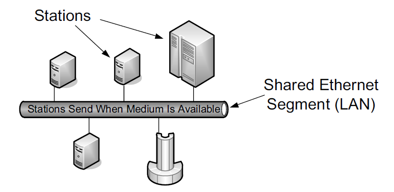
Because multiple stations share the same network, this standard includes a distributed algorithm implemented in each Ethernet network interface that controls when a station gets to send data it has. The particular method, known as carrier sense, multiple access with collision detection (CSMA/CD), mediates which computers can access the shared medium (cable) without any other special agreement or synchronization. This relative simplicity helped to promote the low cost and resulting popularity of Ethernet technology.
With CSMA/CD, a station (e.g., computer) first looks for a signal currently being sent on the network and sends its own frame when the network is free. This is the "carrier sense" portion of the protocol. If some other station happens to send at the same time, the resulting overlapping electrical signal is detected as a collision. In this case, each station waits a random amount of time before trying again. The amount of time is selected by drawing from a uniform probability distribution that doubles in length each time a subsequent collision is detected.
Eventually, each station gets its chance to send or times out trying after some number of attempts (16 in the case of conventional Ethernet). With CSMA/CD, only one frame is traveling on the network at any given time. Access methods such as CSMA/CD are more formally called Media Access Control (MAC) protocols. There are many types of MAC protocols; some are based on having each station try to use the network independently (contention-based protocols like CSMA/ CD), and others are based on prearranged coordination (e.g., by allocating time slots for each station to send).
By the early 1990s, the shared cable had largely been replaced by twisted-pair wiring (resembling telephone wires and often called "10BASE-T"). With the development of 100Mb/s (also called "fast Ethernet," the most popular version of which is known as "100BASE-TX"), contention-based MAC protocols have become less popular. Instead, the wiring between each LAN station is often not shared but instead provides a dedicated electrical path in a star topology. This can be accomplished with Ethernet switches.
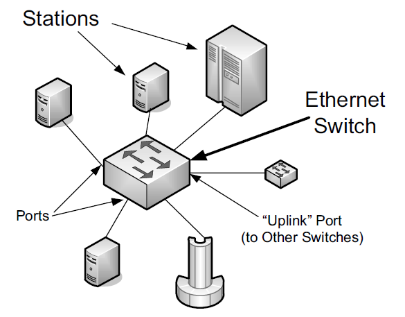
At present, switches are commonly used, providing each Ethernet station with the ability to send and receive data simultaneously (called "full-duplex Ethernet").
One of the most popular technologies used to access the Internet today is wireless networking, the most common for wireless local area networks (WLANs) being an IEEE standard known as Wireless Fidelity or Wi-Fi, and sometimes called "wireless Ethernet" or 802.11. Although this standard is distinct from the 802 wired Ethernet standards, the frame format and general interface are largely borrowed from 802.3, and all are part of the set of IEEE 802 LAN standards. Thus, most of the capabilities used by TCP/IP for Ethernet networks are also used for Wi-Fi networks.
1.1. The IEEE 802 LAN/MAN Standards
In the world of IEEE standards, standards with the prefix 802 define the operations of LANs and MANs. The most popular 802 standards today include 802.3 (essentially Ethernet) and 802.11 (WLAN/Wi-Fi).
| Name | Description | Official Reference |
|---|---|---|
802.1ak |
Multiple Registration Protocol (MRP) |
[802.1AK-2007] |
802.1AE |
MAC Security (MACSec) |
[802.1AE-2006] |
802.1AX |
Link Aggregation (formerly 802.3ad) |
[802.1AX-2008] |
802.1d |
MAC Bridges |
[802.1D-2004] |
802.1p |
Traffic classes/priority/QoS |
[802.1D-2004] |
802.1q |
Virtual Bridged LANs/Corrections to MRP |
[802.1Q-2005/Cor1-2008] |
802.1s |
Multiple Spanning Tree Protocol (MSTP) |
[802.1Q-2005] |
802.1w |
Rapid Spanning Tree Protocol (RSTP) |
[802.1D-2004] |
802.1X |
Port-Based Network Access Control (PNAC) |
[802.1X-2010] |
802.2 |
Logical Link Control (LLC) |
[802.2-1998] |
802.3 |
Baseline Ethernet and 10Mb/s Ethernet |
[802.3-2008] |
802.3u |
100Mb/s Ethernet ("Fast Ethernet") |
[802.3-2008] |
802.3x |
Full-duplex operation and flow control |
[802.3-2008] |
802.3z/802.3ab |
1000Mb/s Ethernet ("Gigabit Ethernet") |
[802.3-2008] |
802.3ae |
10Gb/s Ethernet ("Ten-Gigabit Ethernet") |
[802.3-2008] |
802.3ad |
Link Aggregation |
[802.1AX-2008] |
802.3af |
Power over Ethernet (PoE) (to 15.4W) |
[802.3-2008] |
802.3ah |
Access Ethernet ("Ethernet in the First Mile (EFM)") |
[802.3-2008] |
802.3as |
Frame format extensions (to 2000 bytes) |
[802.3-2008] |
802.3at |
Power over Ethernet enhancements ("PoE+", to 30W) |
[802.3at-2009] |
802.3ba |
40/100Gb/s Ethernet |
[802.3ba-2010] |
802.11a |
54Mb/s Wireless LAN at 5GHz |
[802.11-2007] |
802.11b |
11Mb/s Wireless LAN at 2.4GHz |
[802.11-2007] |
802.11e |
QoS enhancement for 802.11 |
[802.11-2007] |
802.11g |
54Mb/s Wireless LAN at 2.4GHz |
[802.11-2007] |
802.11h |
Spectrum/power management extensions |
[802.11-2007] |
802.11i |
Security enhancements/replaces WEP |
[802.11-2007] |
802.11j |
4.9–5.0GHz operation in Japan |
[802.11-2007] |
802.11n |
6.5–600Mb/s Wireless LAN at 2.4 and 5GHz using optional MIMO and 40MHz channels |
[802.11n-2009] |
802.11s |
(draft) Mesh networking, congestion control |
Under development |
802.11y |
54Mb/s wireless LAN at 3.7GHz (licensed) |
[802.11y-2008] |
802.16 |
Broadband Wireless Access Systems (WiMAX) |
[802.16-2009] |
802.16d |
Fixed Wireless MAN Standard (WiMAX) |
[802.16-2009] |
802.16e |
Fixed/Mobile Wireless MAN Standard (WiMAX) |
[802.16-2009] |
802.16h |
Improved Coexistence Mechanisms |
[802.16h-2010] |
802.16j |
Multihop Relays in 802.16 |
[802.16j-2009] |
802.16k |
Bridging of 802.16 |
[802.16k-2007] |
802.21 |
Media Independent Handovers |
[802.21-2008] |
1.2. The Ethernet Frame Format
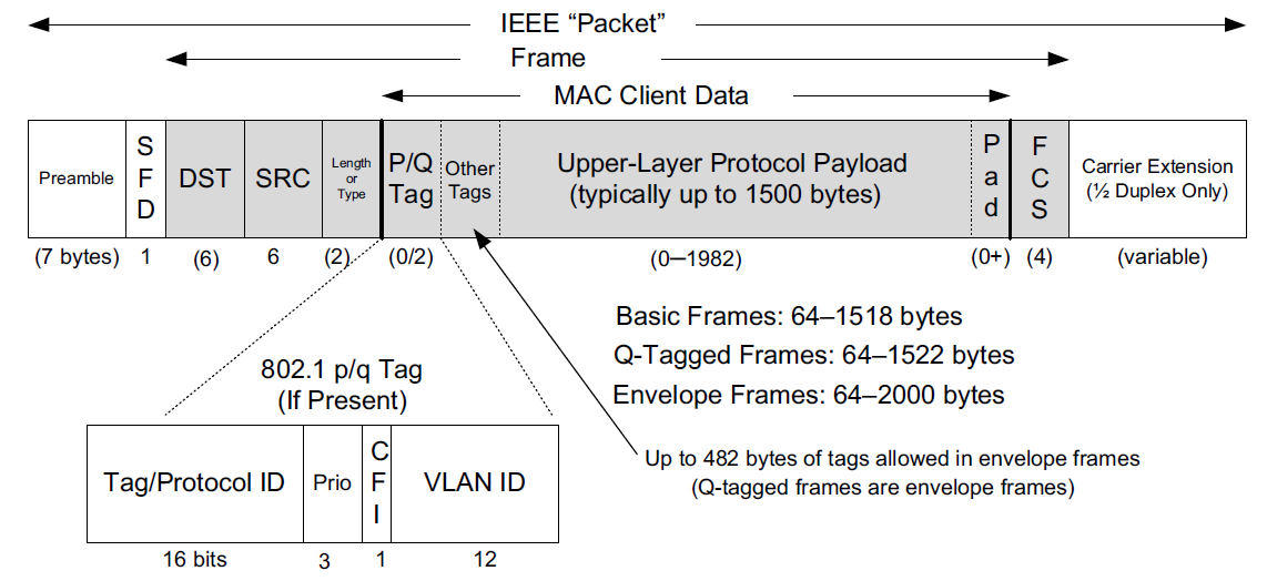
The Ethernet frame begins with a Preamble area used by the receiving interface’s circuitry to determine when a frame is arriving and to determine the amount of time between encoded bits (called clock recovery).
The preamble is a recognizable pattern (0xAA typically), which the receiver can use to recover the clock by the time the start frame delimiter (SFD) is found. The SFD has the fixed value 0xAB.
All Ethernet (802.3) frames are based on a common format.
This basic frame format includes 48-bit (6-byte) Destination (DST) and Source (SRC) Address fields, known by other names such as MAC address, link-layer address, 802 address, hardware address, or physical address. The destination address is also allowed to address more than one station, called broadcast or multicast.
Following the source address is a Type field that doubles as a Length field. Ordinarily, it identifies the type of data that follows the header. Popular values used with TCP/IP networks include IPv4 (0x0800), IPv6 (0x86DD), and ARP (0x0806).
The value 0x8100 indicates a Q-tagged frame (i.e., one that can carry a virtual LAN or VLAN ID according to the 802.1q standard).
The size of a basic Ethernet frame is 1518 bytes, but the more recent standard extended this size to 2000 bytes.
Following the Destination and Source Address fields, [802.3-2008] provides for a variable number of tags that contain various protocol fields defined by other IEEE standards. The most common of these are the tags used by 802.1p and 802.1q, which provide for virtual LANs and some quality-of-service (QoS) indicators.
Following the fields discussed so far is the data area or payload portion of the frame. This is the area where higher-layer PDUs such as IP datagrams are placed.
The payload sometimes is padded (appended) with 0 bytes to ensure that the overall frame meets the minimum length requirements.
The final Cyclic Redundancy Check (CRC) or Frame Check Sequence (FCS) field of the Ethernet frame format follows the payload area and provides an integrity check on the frame.
1.2.1. Frame Sizes
There is both a minimum and a maximum size of Ethernet frames.
The minimum is 64 bytes, requiring a minimum data area (payload) length of 48 bytes (no tags).
In cases where the payload is smaller, pad bytes (value 0) are appended to the end of the payload portion to ensure that the minimum length is enforced.
The maximum frame size of conventional Ethernet is 1518 bytes (including the 4-byte CRC and 14-byte header).
This value represents a sort of trade-off: if a frame contains an error (detected on receipt by an incorrect CRC), only 1.5KB need to be retransmitted to repair the problem. On the other hand, the size limits the MTU to not more than 1500 bytes.
In order to send a larger message, multiple frames are required (e.g., 64KB, a common larger size used with TCP/IP networks, would require at least 44 frames).
One way to improve efficiency when moving large amounts of data across an Ethernet would be to make the frame size larger accomplished using Ethernet jumbo frames [JF], a nonstandard extension to Ethernet that typically allows the frame size to be as large as 9000 bytes. Others make use of so-called super jumbo frames, which are usually understood to carry more than 9000 bytes.
1.3. 802.1p/q: Virtual LANs and QoS Tagging
With the growing use of switched Ethernet, it has become possible to interconnect every computer at a site on the same Ethernet LAN.
The advantage of doing this is that any host can directly communicate with any other host, using IP and other network-layer protocols, and requiring little or no administrator configuration.
In addition, broadcast and multicast traffic is distributed to all hosts that may wish to receive it without having to set up special multicast routing protocols.
While these represent some of the advantages of placing many stations on the same Ethernet, having broadcast traffic go to every computer can create an undesirable amount of network traffic when many hosts use broadcast, and there may be some security reasons to disallow complete any-to-any station communication.
To address some of these problems with running large, multiuse switched networks, IEEE extended the 802 LAN standards with a capability called virtual LANs (VLANs) in a standard known as 802.1q [802.1Q-2005]. Compliant Ethernet switches isolate traffic among hosts to common VLANs.
Note that because of this isolation, two hosts attached to the same switch but operating on different VLANs require a router between them for traffic to flow.
Combination switch/router devices have been created to address this need, and ultimately the performance of routers has been improved to match the performance of VLAN switching.
Thus, the appeal of VLANs has diminished somewhat, in favor of modern high-performance routers. Nonetheless, they are still used, remain popular in some environments, and are important to understand.
Several methods are used to specify the station-to-VLAN mapping.
-
Assigning VLANs by port is a simple and common method, whereby the switch port to which the station is attached is assigned a particular VLAN, so any station so attached becomes a member of the associated VLAN.
-
Other options include MAC address- based VLANs that use tables within Ethernet switches to map a station’s MAC address to a corresponding VLAN. This can become difficult to manage if stations change their MAC addresses (which they do sometimes, thanks to the behavior of some users).
-
IP addresses can also be used as a basis for assigning VLANs.
When stations in different VLANs are attached to the same switch, the switch ensures that traffic does not leak from one VLAN to another, irrespective of the types of Ethernet interfaces being used by the stations.
When multiple VLANs must span multiple switches (trunking), it becomes necessary to label Ethernet frames with the VLAN to which they belong before they are sent to another switch.
-
Support for this capability uses a tag called the VLAN tag (or header), which holds 12 bits of VLAN identifier (providing for 4096 VLANs, although VLAN 0 and VLAN 4095 are reserved).
-
It also contains 3 bits of priority for supporting QoS, defined in the 802.1p standard.
In many cases, the administrator must configure the ports of the switch to be used to send 802.1p/q frames by enabling trunking on the appropriate ports. To make this job somewhat easier, some switches support a native VLAN option on trunked ports, meaning that untagged frames are by default associated with the native VLAN. Trunking ports are used to interconnect VLAN-capable switches, and other ports are typically used to attach stations. Some switches also support proprietary methods for VLAN trunking (e.g., the Cisco Inter-Switch Link (ISL) protocol).
$ sudo ip link show ens32
2: ens32: <BROADCAST,MULTICAST,UP,LOWER_UP> mtu 1500 qdisc pfifo_fast state UP mode DEFAULT group default qlen 1000
    link/ether 00:0c:29:8c:df:3f brd ff:ff:ff:ff:ff:ff
    altname enp2s0

$ sudo ip link add link ens32 name ens32.5 type vlan id 5
$ sudo ip -d link show ens32.5
4: ens32.5@ens32: <BROADCAST,MULTICAST> mtu 1500 qdisc noop state DOWN mode DEFAULT group default qlen 1000
    link/ether 00:0c:29:8c:df:3f brd ff:ff:ff:ff:ff:ff promiscuity 0 minmtu 0 maxmtu 65535
    vlan protocol 802.1Q id 5 <REORDER_HDR> addrgenmode eui64 numtxqueues 1 numrxqueues 1 gso_max_size 65536 gso_max_segs 65535

$ sudo ip addr add 192.168.91.200/24 brd 192.168.91.255 dev ens32.5
$ sudo ip link set dev ens32.5 up
$ sudo ip a s ens32.5
4: ens32.5@ens32: <BROADCAST,MULTICAST,UP,LOWER_UP> mtu 1500 qdisc noqueue state UP group default qlen 1000
    link/ether 00:0c:29:8c:df:3f brd ff:ff:ff:ff:ff:ff
    inet 192.168.91.200/24 brd 192.168.91.255 scope global ens32.5
       valid_lft forever preferred_lft forever
    inet6 fe80::20c:29ff:fe8c:df3f/64 scope link
       valid_lft forever preferred_lft forever

$ sudo ip link delete ens32.5
$ sudo ip l
1: lo: <LOOPBACK,UP,LOWER_UP> mtu 65536 qdisc noqueue state UNKNOWN mode DEFAULT group default qlen 1000
    link/loopback 00:00:00:00:00:00 brd 00:00:00:00:00:00
2: ens32: <BROADCAST,MULTICAST,UP,LOWER_UP> mtu 1500 qdisc pfifo_fast state UP mode DEFAULT group default qlen 1000
    link/ether 00:0c:29:8c:df:3f brd ff:ff:ff:ff:ff:ff
    altname enp2s0
1.4. 802.1AX: Link Aggregation (Formerly 802.3ad)
Some systems equipped with multiple network interfaces are capable of bonding or link aggregation.
With link aggregation, two or more interfaces are treated as one in order to achieve greater reliability through redundancy or greater performance by splitting (striping) data across multiple interfaces.
The IEEE Amendment 802.1AX [802.1AX-2008] defines the most common method for performing link aggregation and the Link Aggregation Control Protocol (LACP) to manage such links. LACP uses IEEE 802 frames of a particular format (called LACPDUs).
Using link aggregation on Ethernet switches that support it can be a cost effective alternative to investing in switches with high-speed network ports. If more than one port can be aggregated to provide adequate bandwidth, higherspeed ports may not be required.
Link aggregation may be supported not only on network switches but across multiple network interface cards (NICs) on a host computer.
Often, aggregated ports must be of the same type, operating in the same mode (i.e., half- or full-duplex).
Linux has the capability to implement link aggregation (bonding) across different types of devices using the following commands:
1.5. Full Duplex, Power Save, Autonegotiation, and 802.1X Flow Control
When Ethernet was first developed, it operated only in half-duplex mode using a shared cable. That is, data could be sent only one way at one time, so only one station was sending a frame at any given point in time. With the development of switched Ethernet, the network was no longer a single piece of shared wire, but instead many sets of links. As a result, multiple pairs of stations could exchange data simultaneously.
In Linux, the ethtool program can be used to query whether full duplex is supported and whether it is being used:
$ sudo ethtool ens32
Settings for ens32:
	Supported ports: [ TP ]
	Supported link modes:   10baseT/Half 10baseT/Full
	                        100baseT/Half 100baseT/Full
	                        1000baseT/Full
	Supported pause frame use: No
	Supports auto-negotiation: Yes
	Supported FEC modes: Not reported
	Advertised link modes:  10baseT/Half 10baseT/Full
	                        100baseT/Half 100baseT/Full
	                        1000baseT/Full
	Advertised pause frame use: No
	Advertised auto-negotiation: Yes
	Advertised FEC modes: Not reported
	Speed: 1000Mb/s
	Duplex: Full
	Auto-negotiation: on
	Port: Twisted Pair
	PHYAD: 0
	Transceiver: internal
	MDI-X: off (auto)
	Supports Wake-on: d
	Wake-on: d
        Current message level: 0x00000007 (7)
                               drv probe link
	Link detected: yes
1.6. Link-Layer Flow Control
Operating an extended Ethernet LAN in full-duplex mode and across segments of different speeds may require the switches to buffer (store) frames for some period of time.
For example, when multiple stations send to the same destination (called output port contention).
-
If the aggregate traffic rate headed for a station exceeds the station’s link rate, frames start to be stored in the intermediate switches.
-
If this situation persists for a long time, frames may be dropped.
One way to mitigate this situation is to apply flow control to senders (i.e., slow them down).
Some Ethernet switches (and interfaces) implement flow control by sending special signal frames between switches and NICs.
Flow control signals to the sender that it must slow down its transmission rate, although the specification leaves the details of this to the implementation. Ethernet uses an implementation of flow control called PAUSE messages (also called PAUSE frames), specified by 802.3x [802.3-2008].
2. Bridges and Switches
The IEEE 802.1d standard specifies the operation of bridges, and thus switches, which are essentially high-performance bridges.
A bridge or switch is used to join multiple physical link-layer networks (e.g., a pair of physical Ethernet segments) or groups of stations.
The most basic setup involves connecting two switches to form an extended LAN.
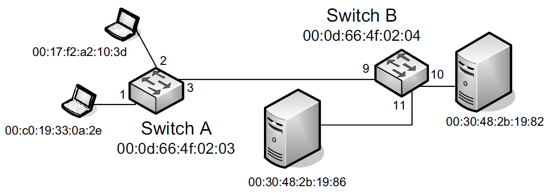
Switches A and B in the figure have been interconnected to form an extended LAN.
Note that every network element, including each switch, has its own MAC address.
Nonlocal MAC addresses are learned by each bridge over time so that eventually every switch knows the port upon which every station can be reached, which are stored in tables (called filtering databases) within each switch on a per-port (and possibly per-VLAN) basis.
| Switch A’s Database | Switch B’s Database | ||
|---|---|---|---|
Station |
Port |
Station |
Port |
00:17:f2:a2:10:3d |
2 |
00:17:f2:a2:10:3d |
9 |
00:c0:19:33:0a:2e |
1 |
00:c0:19:33:0a:2e |
9 |
00:0d:66:4f:02:03 |
00:0d:66:4f:02:03 |
9 |
|
00:0d:66:4f:02:04 |
3 |
00:0d:66:4f:02:04 |
|
00:30:48:2b:19:82 |
3 |
00:30:48:2b:19:82 |
10 |
00:30:48:2b:19:86 |
3 |
00:30:48:2b:19:86 |
11 |
When a switch (bridge) is first turned on, its database is empty, so it does not know the location of any stations except itself.
Whenever it receives a frame destined for a station other than itself, it makes a copy for each of the ports other than the one on which the frame arrived and sends a copy of the frame out of each one.
If switches (bridges) never learned the location of stations, every frame would be delivered across every network segment, leading to unwanted overhead.
The learning capability reduces overhead significantly and is a standard feature of switches and bridges.
Today, most operating systems support the capability to bridge between network interfaces, meaning that a standard computer with multiple interfaces can be used as a bridge.
In Windows, for example, interfaces may be bridged together by navigating to the Network Connections menu from the Control Panel, highlighting the interfaces to bridge, right-clicking the mouse, and selecting Bridge Connections.
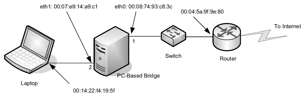
The simple network uses a Linux-based PC with two Ethernet ports as a bridge. Attached to port 2 is a single station, and the rest of the network is attached to port 1. The following commands enable the bridge:
root@node-1:~# ip link
1: lo: <LOOPBACK,UP,LOWER_UP> mtu 65536 qdisc noqueue state UNKNOWN mode DEFAULT group default qlen 1000
    link/loopback 00:00:00:00:00:00 brd 00:00:00:00:00:00
2: ens32: <BROADCAST,MULTICAST,UP,LOWER_UP> mtu 1500 qdisc pfifo_fast state UP mode DEFAULT group default qlen 1000
    link/ether 00:0c:29:85:26:07 brd ff:ff:ff:ff:ff:ff
3: ens33: <BROADCAST,MULTICAST,UP,LOWER_UP> mtu 1500 qdisc pfifo_fast state UP mode DEFAULT group default qlen 1000
    link/ether 00:0c:29:85:26:1b brd ff:ff:ff:ff:ff:ff
4: ens34: <BROADCAST,MULTICAST,UP,LOWER_UP> mtu 1500 qdisc pfifo_fast state UP mode DEFAULT group default qlen 1000
    link/ether 00:0c:29:85:26:11 brd ff:ff:ff:ff:ff:ff
5: ens35: <BROADCAST,MULTICAST> mtu 1500 qdisc noop state DOWN mode DEFAULT group default qlen 1000
    link/ether 00:0c:29:85:26:25 brd ff:ff:ff:ff:ff:ff
6: ens36: <BROADCAST,MULTICAST> mtu 1500 qdisc noop state DOWN mode DEFAULT group default qlen 1000
    link/ether 00:0c:29:85:26:2f brd ff:ff:ff:ff:ff:ff

root@node-1:~# brctl addbr br0  # apt install bridge-utils
root@node-1:~# brctl addif br0 ens33
root@node-1:~# brctl addif br0 ens34
root@node-1:~# brctl addif br0 ens35

root@node-1:~# brctl show
bridge name	bridge id		STP enabled	interfaces
br0		8000.000c29852611	no		ens33
							ens34
							ens35
root@node-1:~# ip link set br0 up
root@node-1:~# brctl showmacs br0
port no	mac addr		is local?	ageing timer
  1	00:0c:29:85:26:07	no		   0.06
  2	00:0c:29:85:26:11	yes		   0.00
  2	00:0c:29:85:26:11	yes		   0.00
  1	00:0c:29:85:26:1b	yes		   0.00
  1	00:0c:29:85:26:1b	yes		   0.00
  3	00:0c:29:85:26:25	yes		   0.00
  3	00:0c:29:85:26:25	yes		   0.00
  1	00:0c:29:8c:df:49	no		   0.01
  2	00:50:56:c0:00:08	no		   0.03
3. Wireless LANs—IEEE 802.11(Wi-Fi)
One of the most popular technologies being used to access the Internet today is wireless fidelity (Wi-Fi), also known by its IEEE standard name 802.11, effectively a wireless version of Ethernet.
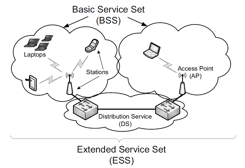
The network includes a number of stations (STAs). Typically stations are organized with a subset operating also as access points (APs).
An AP and its associated stations are called a basic service set (BSS). The APs are generally connected to each other using a wired distribution service (called a DS, basically a "backbone"), forming an extended service set (ESS). This setup is commonly termed infrastructure mode.
The 802.11 standard also provides for an ad hoc mode. In this configuration there is no AP or DS; instead, direct station-to-station (peer-to-peer) communication takes place. In IEEE terminology, the STAs participating in an ad hoc network form an independent basic service set (IBSS).
A WLAN formed from a collection of BSSs and/or IBSSs is called a service set, identified by a service set identifier (SSID).
An extended service set identifier (ESSID) is an SSID that names a collection of connected BSSs and is essentially a name for the LAN that can be up to 32 characters long.
3.1. 802.11 Frames
There is one common overall frame format for 802.11 networks but multiple types of frames. Not all the fields are present in every type of frame.
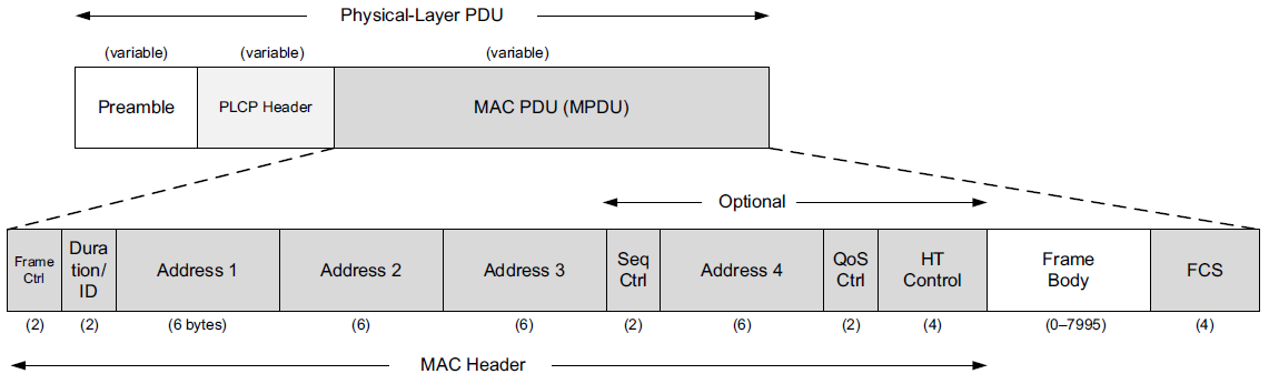
The frame shown includes a preamble for synchronization, which depends on the particular variant of 802.11 being used.
Next, the Physical Layer Convergence Procedure (PLCP) header provides information about the specific physical layer in a somewhat PHY-independent way.
-
The PLCP portion of the frame is generally transmitted at a lower data rate than the rest of the frame.
-
This serves two purposes:
-
to improve the probability of correct delivery (lower speeds tend to have better error resistance)
-
and to provide compatibility with and protection from interference from legacy equipment that may operate in the same area at slower rates.
-
The MAC PDU (MPDU) corresponds to a frame similar to Ethernet, but with some additional fields.
-
At the head of the MPDU is the Frame Control Word, which includes a 2-bit Type field identifying the frame type.
-
There are three types of frames: management frames, control frames, and data frames.
3.1.1. Management Frames
Management frames are used for creating, maintaining, and ending associations between stations and access points. They are also used to determine whether encryption is being used, what the name (SSID or ESSID) of the network is, what transmission rates are supported, and a common time base. These frames are used to provide the information necessary when a Wi-Fi interface "scans" for nearby access points.
Scanning is the procedure by which a station discovers available networks and related configuration information.
Linux# iwlist wlan0 scan
wlan0 Scan completed :
    Cell 01 - Address: 00:02:6F:20:B5:84
        ESSID:"Grizzly-5354-Aries-802.11b/g"
        Mode:Master
        Channel:4
            Frequency:2.427 GHz (Channel 4)
        Quality=5/100 Signal level=47/100
        Encryption key:on
        IE: WPA Version 1
            Group Cipher : TKIP
            Pairwise Ciphers (2) : CCMP TKIP
            Authentication Suites (1) : PSK
        Bit Rates:1 Mb/s; 2 Mb/s; 5.5 Mb/s; 11 Mb/s;
            6 Mb/s; 12 Mb/s; 24 Mb/s; 36 Mb/s; 9 Mb/s;
            18 Mb/s; 48 Mb/s; 54 Mb/s
        Extra:tsf=0000009d832ff037
Here we see the result of a hand-initiated scan using wireless interface wlan0.
-
An AP with MAC address 00:02:6F:20:B5:84 is acting as a master (i.e., is acting as an AP in infrastructure mode).
-
It is broadcasting the ESSID "Grizzly- 5354-Aries-802.11b/g" on channel 4 (2.427GHz).
-
The quality and signal level give indications of how well the scanning station is receiving a signal from the AP, although the meaning of these values varies among manufacturers.
-
WPA encryption is being used on this link,
-
and bit rates from 1Mb/s to 54Mb/s are available.
-
The tsf (time sync function) value indicates the AP’s notion of time, which is used for synchronizing various features such as power saving mode.
PS C:\> netsh wlan show networks mode=bssid
Interface name : Wi-Fi
There are 1 networks currently visible.
SSID 1 : BAOLAND
    Network type            : Infrastructure
    Authentication          : WPA2-Personal
    Encryption              : CCMP
    BSSID 1                 : 9c:a6:15:6e:93:dd
         Signal             : 60%
         Radio type         : 802.11n
         Channel            : 11
         Basic rates (Mbps) : 1 2 5.5 11
         Other rates (Mbps) : 6 9 12 18 24 36 48 54
3.1.2. Control Frames: RTS/CTS and ACKs
Control frames are used to handle a form of flow control as well as acknowledgments for frames.
Flow control helps ensure that a receiver can slow down a sender that is too fast.
Acknowledgments help a sender know what frames have been received correctly.
These concepts also apply to TCP at the transport layer.
802.11 networks support optional request-to-send (RTS)/clear-to-send (CTS) moderation of transmission for flow control.
-
When these are enabled, prior to sending a data frame a station transmits an RTS frame, and when the recipient is willing to receive additional traffic, it responds with a CTS.
-
After the RTS/CTS exchange, the station has a window of time (identified in the CTS frame) to transmit data frames that are acknowledged when successfully received.
-
Such transmission coordination schemes are common in wireless networks and mimic the flow control signaling that has been used on wired serial lines for years (sometimes called hardware flow control).
In wired Ethernet networks, the absence of a collision indicates that a frame has been received correctly with high probability.
In wireless networks, there is a wider range of reasons a frame may not be delivered correctly, such as insufficient signal or interference.
To help address this potential problem, 802.11 extends the 802.3 retransmission scheme with a retransmission/acknowledgment (ACK) scheme.
-
An acknowledgment is expected to be received within a certain amount of time for each unicast frame sent (802.11a/b/g) or each group of frames sent (802.11n or 802.11e with "block ACKs").
-
Multicast and broadcast frames do not have associated ACKs to avoid "ACK implosion".
-
Failure to receive an ACK within the specified time results in retransmission of the frame(s).
3.1.3. Data Frames, Fragmentation, and Aggregation
Most frames seen on a busy network are data frames, which do what one would expect—carry data.
Typically, there is a one-to-one relationship between 802.11 frames and the link-layer (LLC) frames made available to higher-layer protocols such as IP.
However, 802.11 supports frame fragmentation, which can divideframes into multiple fragments. With the 802.11n specification, it also supports frame aggregation, which can be used to send multiple frames together with less overhead.
3.2. Wi-Fi Security
There has been considerable evolution in the security model for 802.11 networks.
In its early days, 802.11 used an encryption method known as wired equivalent privacy (WEP).
-
WEP was later shown to be so weak that some replacement was required.
Industry responded with Wi-Fi protected access (WPA), which replaced the way keys are used with encrypted blocks.
-
In WPA, a scheme called the Temporal Key Integrity Protocol (TKIP) ensures, among other things, that each frame is encrypted with a different encryption key.
-
It also includes a message integrity check, called Michael, that fixed one of the major weaknesses in WEP.
-
WPA was created as a placeholder that could be used on fielded WEP-capable equipment by way of a firmware upgrade while the IEEE 802.11i standards group worked on a stronger standard that was ultimately absorbed into Clause 8 of [802.11-2007] and dubbed "WPA2" by industry.
Both WEP and WPA use the RC4 encryption algorithm. WPA2 uses the Advanced Encryption Standard (AES) algorithm.
| Name/Standard | Cipher | Key Stream Management | Authentication |
|---|---|---|---|
WEP (pre-RSNA) |
RC4 |
(WEP) |
PSK, (802.1X/EAP) |
WPA |
RC4 |
TKIP |
PSK, 802.1X/EAP |
WPA2/802.11(i) |
CCMP |
CCMP, (TKIP) |
PSK, 802.1X/EAP |
3.3. Wi-Fi Mesh (802.11s)
The IEEE is working on the 802.11s standard, which covers Wi-Fi mesh operation. With mesh operation, wireless stations can act as data-forwarding agents (like APs).
The standard is not yet complete as of writing (mid-2011). The draft version of 802.11s defines the Hybrid Wireless Routing Protocol (HWRP), based in part on the IETF standards for Ad-Hoc On-Demand Distance Vector (AODV) routing [RFC3561] and the Optimized Link State Routing (OLSR) protocol [RFC3626].
4. Point-to-Point Protocol (PPP)
PPP stands for the Point-to-Point Protocol [RFC1661][RFC1662][RFC2153]. It is a popular method for carrying IP datagrams over serial links—from low-speed dial-up modems to high-speed optical links [RFC2615]. It is widely deployed by some DSL service providers, which also use it for assigning Internet system parameters (e.g., initial IP address and domain name server).
PPP should be considered more of a collection of protocols than a single protocol.
-
It supports a basic method to establish a link, called the Link Control Protocol (LCP),
-
as well as a family of NCPs, used to establish network-layer links for various kinds of protocols,
including IPv4 and IPv6 and possibly non-IP protocols, after LCP has established the basic link.
-
A number of related standards cover control of compression and encryption for PPP,
and a number of authentication methods can be employed when a link is brought up.
4.1. Link Control Protocol (LCP)
The LCP portion of PPP is used to establish and maintain a low-level two-party communication path over a point-to-point link. PPP’s operation therefore need be concerned only with two ends of a single link; it does not need to handle the problem of mediating access to a shared resource like the MAC-layer protocols of Ethernet and Wi-Fi.
PPP generally, and LCP more specifically, imposes minimal requirements on the underlying point-to-point link. The link must support bidirectional operation (LCP uses acknowledgments) and operate either asynchronously or synchronously.
Typically, LCP establishes a link using a simple bit-level framing format based on the High-Level Data Link Control (HDLC) protocol.
-
HDLC was already a well-established framing format by the time PPP was designed [ISO3309] [ISO4335].
-
IBM modified it to form Synchronous Data Link Control (SDLC), a protocol used as the link layer in its proprietary System Network Architecture (SNA) protocol suite.
-
HDLC was also used as the basis for the LLC standard in 802.2 and ultimately for PPP as well.
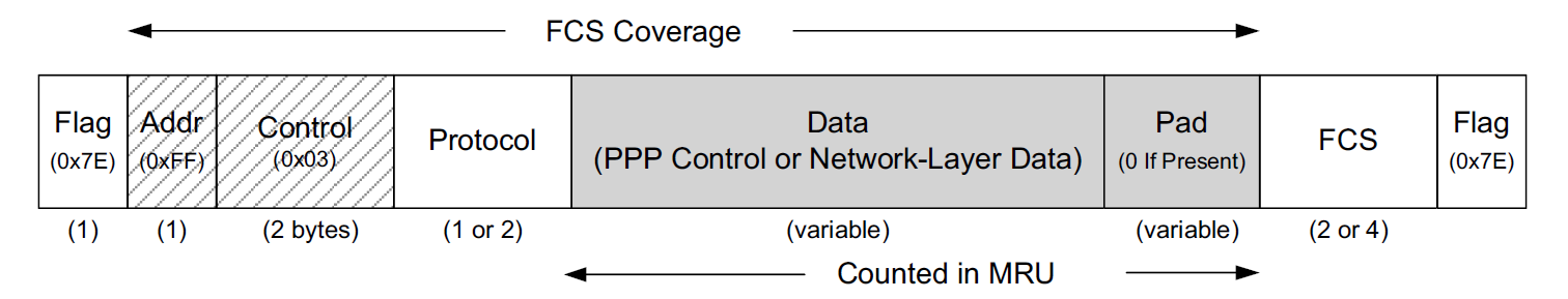
The PPP frame format, in the common case when HDLC-like framing is used, is surrounded by two 1-byte Flag fields containing the fixed value 0x7E. These fields are used by the two stations on the ends of the point-to-point link for finding the beginning and end of the frame.
A small problem arises if the value 0x7E itself occurs inside the frame. This is handled in one of two ways, depending on whether PPP is operating over an asynchronous or a synchronous link.
-
For asynchronous links, PPP uses character stuffing (also called byte stuffing).
If the flag character appears elsewhere in the frame, it is replaced with the 2-byte sequence 0x7D5E (0x7D is known as the "PPP escape character").
If the escape character itself appears in the frame, it is replaced with the 2-byte sequence 0x7D5D.
Thus, the receiver replaces 0x7D5E with 0x7E and 0x7D5D with 0x7D upon receipt.
-
On synchronous links (e.g., T1 lines, T3 lines), PPP uses bit stuffing.
After the first Flag field, PPP adopts the HDLC Address (Addr) and Control fields.
-
In HDLC, the Address field would specify which station is being addressed, but because PPP is concerned only with a single destination, this field is always defined to have the value 0xFF (all stations).
-
The Control field in HDLC is used to indicate frame sequencing and retransmission behavior.
As these link-layer reliability functions are not ordinarily implemented by PPP, the Control field is set to the fixed value 0x03.
Because both the Address and Control fields are fixed constants in PPP, they are often omitted during transmission with an option called Address and Control Field Compression (ACFC), which essentially eliminates the two fields.
The Protocol field of the PPP frame indicates the type of data being carried.
-
Many different types of protocols can be carried in a PPP frame.
-
The official list and the assigned number used in the Protocol field are given by the "Point-to-Point Protocol Field Assignments" document.
-
In some circumstances the Protocol field can be compressed to a single byte, if the Protocol Field Compression (PFC) option is negotiated successfully during link establishment.
The final portion of the PPP frame contains a 16-bit FCS (a CRC16, with generator polynomial 10001000000100001) covering the entire frame except the FCS field itself and Flag bytes.
4.1.1. LCP Operation
LCP has a simple encapsulation beyond the basic PPP packet.
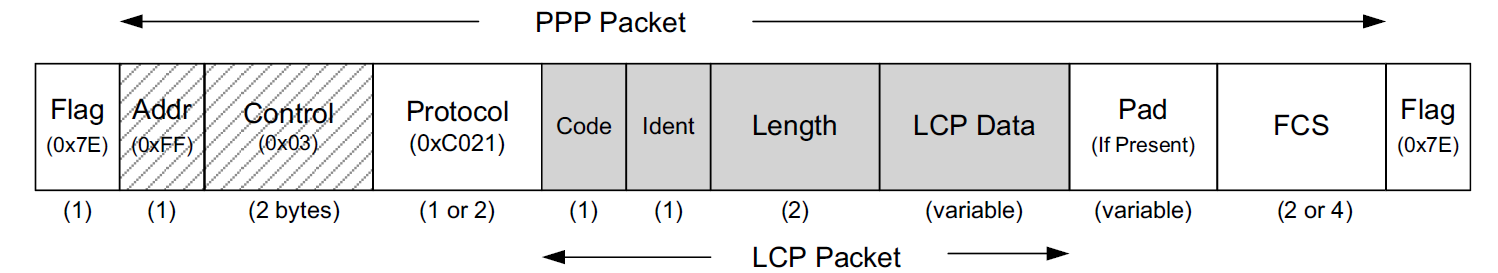
The PPP Protocol field value for LCP is always 0xC021, which is not eliminated using PFC, so as to minimize ambiguity.
The Ident field is a sequence number provided by the sender of LCP request frames and is incremented for each subsequent message.
When forming a reply (ACK, NACK, or REJECT response), this field is constructed by copying the value included in the request to the response packet. In this fashion, the requesting side can identify replies to the appropriate request by matching identifiers.
The Code field gives the type of operation being either requested or responded to: configure-request (0x01), configure-ACK (0x02), configure-NACK (0x03), configure-REJECT (0x04), terminate-request (0x05), terminate-ACK (0x06), code-REJECT (0x07), protocol-REJECT (0x08), echo-request (0x09), echo-reply (0x0A), discard-request (0x0B), identification (0x0C), and time-remaining (0x0D).
Generally, ACK messages indicate acceptance of a set of options, and NACK messages indicate a partial rejection with suggested alternatives. A REJECT message rejects one or more options entirely. A rejected code indicates that one of the field values contained in a previous packet is unknown.
The Length field gives the length of the LCP packet in bytes and is not permitted to exceed the link’s maximum received unit (MRU), a form of maximum advised frame limit. Note that the Length field is part of the LCP protocol; the PPP protocol in general does not provide such a field.
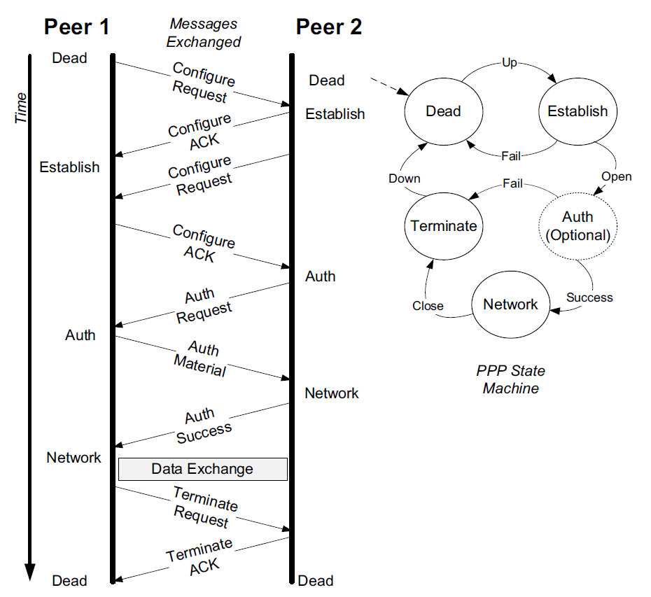
The main job of LCP is to bring up a point-to-point link to a minimal level.
-
Configure messages cause each end of the link to start the basic configuration procedure and establish agreed-upon options.
-
Termination messages are used to clear a link when complete.
LCP also provides some additional features mentioned previously.
-
Echo Request/Reply messages may be exchanged anytime a link is active by LCP in order to verify operation of the peer.
-
The Discard Request message can be used for performance measurement; it instructs the peer to discard the packet without responding.
-
The Identification and Time-Remaining messages are used for administrative purposes: to know the type of the peer system and to indicate the amount of time allowed for the link to remain established (e.g., for administrative or security reasons).
4.1.2. Network Control Protocols (NCPs)
-
For IPv4, the NCP is called the IP Control Protocol (IPCP) [RFC1332].
-
For IPv6, the NCP is IPV6CP [RFC5072].
Once LCP has completed its link establishment and authentication, each end of the link is in the Network state and may proceed to negotiate a network-layer association using zero or more NCPs (one, such as IPCP, is typical).
-
IPCP, the standard NCP for IPv4, can be used to establish IPv4 connectivity over a link and configure Van Jacobson header compression (VJ compression) [RFC1144].
-
IPCP packets may be exchanged after the PPP state machine has reached the Network state.
-
IPCP packets use the same packet exchange mechanism and packet format as LCP, except the Protocol field is set to 0x8021, and the Code field is limited to the range 0–7.
These values of the Code field correspond to the message types: vendor-specific (see [RFC2153]), configure-request, configure-ACK, configure-REJECT, terminate-request, terminate-ACK, and code-REJECT.
-
IPCP can negotiate a number of options, including an IP compression protocol (2), the IPv4 address (3), and Mobile IPv4 [RFC2290] (4).
Other options are available for learning the location of primary and secondary domain name servers.
IPV6CP uses the same packet exchange and format as LCP, except it has two different options: interface-identifier and IPv6-compression-protocol.
5. Loopback
Although it may seem surprising, in many cases clients may wish to communicate with servers on the same computer using Internet protocols such as TCP/IP.
To enable this, most implementations support a network-layer loopback capability that typically takes the form of a virtual loopback network interface. It acts like a real network interface but is really a special piece of software provided by the operating system to enable TCP/IP and other communications on the same host computer.
IPv4 addresses starting with 127 are reserved for this, as is the IPv6 address ::1.
Traditionally, UNIX-like systems including Linux assign the IPv4 address of 127.0.0.1 (::1 for IPv6) to the loopback interface and assign it the name localhost.
An IP datagram sent to the loopback interface must not appear on any network.
In Linux, the loopback interface is called lo.
root@node-1:~# ip a s lo
1: lo: <LOOPBACK,UP,LOWER_UP> mtu 65536 qdisc noqueue state UNKNOWN group default qlen 1000
    link/loopback 00:00:00:00:00:00 brd 00:00:00:00:00:00
    inet 127.0.0.1/8 scope host lo
       valid_lft forever preferred_lft forever
    inet6 ::1/128 scope host
       valid_lft forever preferred_lft forever
In Windows, the Microsoft Loopback Adapter is not installed by default, even though IP loopback is still supported. This adapter can be used for testing various network configurations even when a physical network interface is not available.
To install it run the program hdwwiz from the command prompt and add the Microsoft KM-TEST Loopback Adapter manually.
| The Microsoft Loopback Adapter was renamed in Windows 8 and Windows Server 2012. The new name is "Microsoft KM-TEST Loopback Adapter". |
PS C:\> ipconfig /all

Ethernet adapter Ethernet 2:

   Connection-specific DNS Suffix  . :
   Description . . . . . . . . . . . : Microsoft KM-TEST Loopback Adapter
   Physical Address. . . . . . . . . : 02-00-4C-4F-4F-50
   DHCP Enabled. . . . . . . . . . . : Yes
   Autoconfiguration Enabled . . . . : Yes
   Link-local IPv6 Address . . . . . : fe80::12ba:71be:e45b:1870%54(Preferred)
   Autoconfiguration IPv4 Address. . : 169.254.24.54(Preferred)
   Subnet Mask . . . . . . . . . . . : 255.255.0.0
   Default Gateway . . . . . . . . . :
   DHCPv6 IAID . . . . . . . . . . . : 906100812
   DHCPv6 Client DUID. . . . . . . . : 00-01-00-01-28-F5-57-C4-8C-C6-81-FE-82-C4
   DNS Servers . . . . . . . . . . . : fec0:0:0:ffff::1%1
                                       fec0:0:0:ffff::2%1
                                       fec0:0:0:ffff::3%1
   NetBIOS over Tcpip. . . . . . . . : Enabled
6. MTU and Path MTU
When two hosts on the same network are communicating with each other, it is the maximum transmission unit (MTU) of the local link interconnecting them that has a direct effect on the size of datagrams.
When two hosts communicate across multiple networks, each link can have a different MTU. The minimum MTU across the network path comprising all of the links is called the path MTU.
The path MTU between any two hosts need not be constant over time.
-
It depends on the path being used at any time, which can change if the routers or links in the network fail.
-
Also, paths are often not symmetric (i.e., the path from host A to B may not be the reverse of the path from B to A); hence the path MTU need not be the same in the two directions.
7. Tunneling Basics
In some cases it is useful to establish a virtual link between one computer and another across the Internet or other network. VPNs, for example, offer this type of service. The method most commonly used to implement these types of services is called tunneling.
Tunneling, generally speaking, is the idea of carrying lower-layer traffic in higher-layer (or equal-layer) packets.
For example, IPv4 can be carried in an IPv4 or IPv6 packet; Ethernet can be carried in a UDP or IPv4 or IPv6 packet, and so on.
Tunneling turns the idea of strict layering of protocols on its head and allows for the formation of overlay networks (i.e., networks where the "links" are really virtual links implemented in some other protocol instead of physical connections).
There is a great variety of methods for tunneling packets of one protocol and/or layer over another. Three of the more common protocols used to establish tunnels include:
-
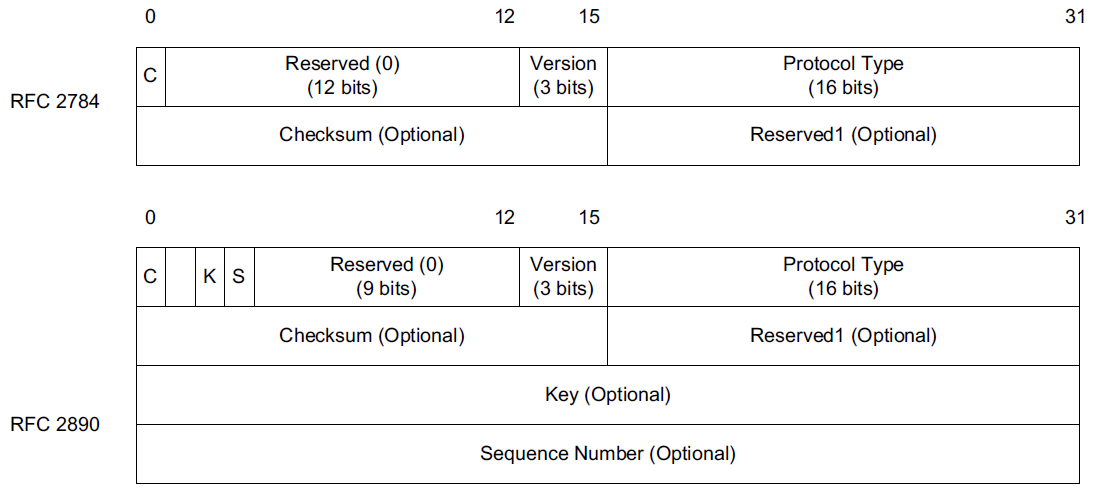
Generic Routing Encapsulation (GRE) [RFC2784],
-
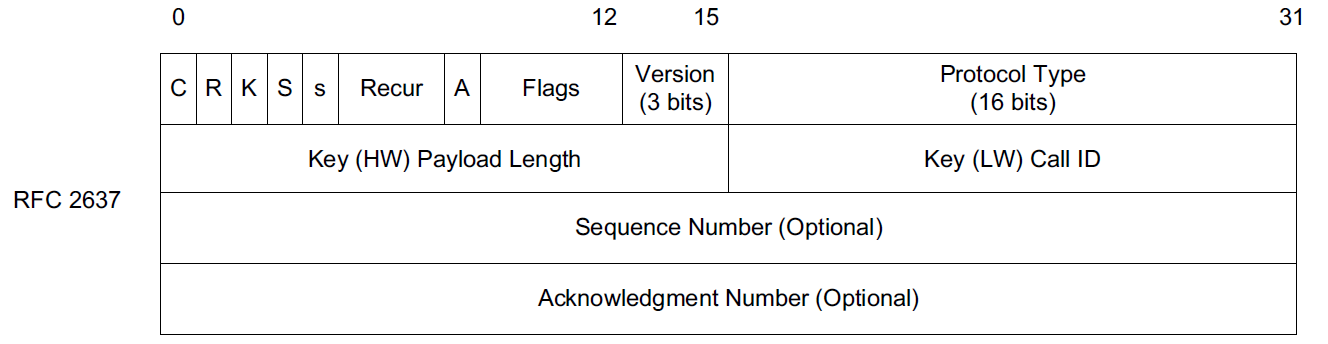
the Microsoft proprietary Point-to-Point Tunneling Protocol (PPTP) [RFC2637],
-
and the Layer 2 Tunneling Protocol (L2TP) [RFC3931].
Although GRE forms the basis for and is used by PPTP, the two protocols serve somewhat different purposes.
-
GRE tunnels are typically used within the network infrastructure to carry traffic between ISPs
or within an enterprise intranet to serve branch offices
and are not necessarily encrypted, although GRE tunnels can be combined with IPsec.
-
PPTP, conversely, is most often used between users and their ISPs or corporate intranets and is encrypted (e.g., using MPPE).
-
PPTP essentially combines GRE with PPP, so GRE can provide the virtual point-to-point link upon which PPP operates.
-
GRE carries its traffic using IPv4 or IPv6 and as such is a layer 3 tunneling technology.
-
PPTP is more often used to carry layer 2 frames (such as Ethernet) so as to emulate a direct LAN (link-layer) connection.
References
-
[1] Kevin Fall, W. Stevens TCP/IP Illustrated: The Protocols, Volume 1. 2nd edition, Addison-Wesley Professional, 2011
-
[2] https://developers.redhat.com/blog/2018/10/22/introduction-to-linux-interfaces-for-virtual-networking