TCP/IP: Internet Protocol
IP is the workhorse protocol of the TCP/IP protocol suite. All TCP, UDP, ICMP, and IGMP data gets transmitted as IP datagrams. IP provides a best-effort, connectionless datagram delivery service.
1. IPv4 and IPv6 Headers
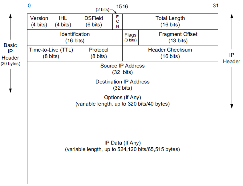
The normal size of the IPv4 header is 20 bytes, unless options are present (which is rare).
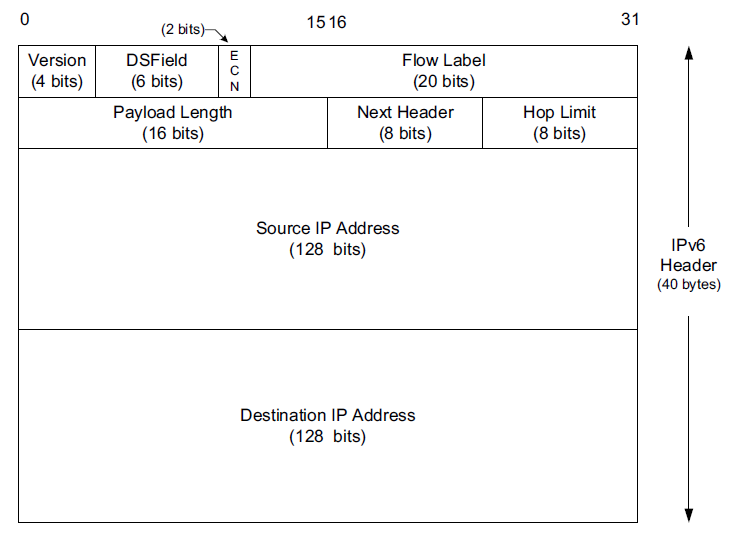
The IPv6 header is twice as large but never has any options, may have extension headers.
The most significant bit of headers and datagrams is numbered 0 at the left, and the least significant bit of a 32-bit value is numbered 31 on the right.
-
The 4 bytes in a 32-bit value are transmitted in the following order: bits 0–7 first, then bits 8–15, then 16–23, and bits 24–31 last.
-
This is called big endian byte ordering, which is the byte ordering required for all binary integers in the TCP/IP headers as they traverse a network. It is also called network byte order.
-
Computer CPUs that store binary integers in other formats, such as the little endian format, must convert the header values into network byte order for transmission and back again for reception.
$ lscpu
Architecture:                    x86_64
CPU op-mode(s):                  32-bit, 64-bit
Byte Order:                      Little Endian
Model name:                      Intel(R) Core(TM) i5-10210U CPU @ 1.60GHz
-
The header is of variable size, limited to fifteen 32-bit words (60 bytes) by the 4-bit IHL field.
-
A typical IPv4 header contains 20 bytes (no options).
-
The source and destination addresses are 32 bits long.
-
Most of the second 32-bit word is used for the IPv4 fragmentation function.
-
A header checksum helps ensure that the fields in the header are delivered correctly to the proper destination but does not protect the data.
-
The IPv6 header is of fixed size (40 bytes) and contains 128-bit source and destination addresses.
-
The Next Header field is used to indicate the presence and types of additional extension headers that follow the IPv6 header, forming a daisy chain of headers that may include special extensions or processing directives.
-
Application data follows the header chain, usually immediately following a transport-layer header.
1.1. IP Header Fields
The first field (only 4 bits or one nibble wide) is the Version field.
-
It contains the version number of the IP datagram: 4 for IPv4 and 6 for IPv6.
-
The headers for both IPv4 and IPv6 share the location of the Version field but no others.
-
Thus, the two protocols are not directly interoperable—a host or router must handle either IPv4 or IPv6 (or both, called dual stack) separately.
The Internet Header Length (IHL) field is the number of 32-bit words in the IPv4 header, including any options.
-
Because this is also a 4-bit field, the IPv4 header is limited to a maximum of fifteen 32-bit words or 60 bytes.
The normal value of this field (when no options are present) is 5.
-
There is no such field in IPv6 because the header length is fixed at 40 bytes.
Following the header length, the original specification of IPv4 [RFC0791] specified a Type of Service (ToS) byte, and IPv6 [RFC2460] specified the equivalent Traffic Class byte.
-
Use of these never became widespread, so eventually this 8-bit field was split into two smaller parts and redefined by a set of RFCs ([RFC3260] [RFC3168][RFC2474] and others).
-
The first 6 bits are now called the Differentiated Services Field (DS Field), and the last 2 bits are the Explicit Congestion Notification (ECN) field or indicator bits.
-
These RFCs now apply to both IPv4 and IPv6.
-
-
These fields are used for special processing of the datagram when it is forwarded.
The Total Length field is the total length of the IPv4 datagram in bytes.
-
Using this field and the IHL field, we know where the data portion of the datagram starts, and its length.
-
Because this is a 16-bit field, the maximum size of an IPv4 datagram (including header) is 65,535 bytes.
-
Although it is possible to send a 65,535-byte IP datagram, most link layers (such as Ethernet) are not able to carry one this large without fragmenting it (chopping it up) into smaller pieces.
Furthermore, a host is not required to be able to receive an IPv4 datagram larger than 576 bytes.
In IPv6 a host must be able to process a datagram at least as large as the MTU of the link to which it is attached, and the minimum link MTU is 1280 bytes.
When an IPv4 datagram is fragmented into multiple smaller fragments, each of which itself is an independent IP datagram, the Total Length field reflects the length of the particular fragment.
In IPv6, fragmentation is not supported by the header, and the length is instead given by the Payload Length field.
This field measures the length of the IPv6 datagram not including the length of the header; extension headers, however, are included in the Payload Length field.
The Identification field helps indentify each datagram sent by an IPv4 host.
-
To ensure that the fragments of one datagram are not confused with those of another, the sending host normally increments an internal counter by 1 each time a datagram is sent (from one of its IP addresses) and copies the value of the counter into the IPv4 Identification field.
-
The Identification, Flags and Fragment Offset fields are most important for implementing fragmentation.
In IPv6, this field shows up in the Fragmentation extension header.
The Time-to-Live field, or TTL, sets an upper limit on the number of routers through which a datagram can pass.
-
It is initialized by the sender to some value (64 is recommended [RFC1122], although 128 or 255 is not uncommon) and decremented by 1 by every router that forwards the datagram.
-
When this field reaches 0, the datagram is thrown away, and the sender is notified with an ICMP message.
This prevents packets from getting caught in the network forever should an unwanted routing loop occur.
The Protocol field in the IPv4 header contains a number indicating the type of data found in the payload portion of the datagram.
-
The most common values are 17 (for UDP) and 6 (for TCP).
-
This provides a demultiplexing feature so that the IP protocol can be used to carry payloads of more than one protocol type.
-
Although this field originally specified the transport-layer protocol the datagram is encapsulating, it is now understood to identify the encapsulated protocol, which may or not be a transport protocol.
For example, other encapsulations are possible, such as IPv4-in-IPv4 (value 4).
-
The official list of the possible values of the Protocol field is given in the assigned numbers page [AN].
The Next Header field in the IPv6 header generalizes the Protocol field from IPv4.
-
It is used to indicate the type of header following the IPv6 header.
-
This field may contain any values defined for the IPv4 Protocol field, or any of the values associated with the IPv6 extension headers.
Decimal Keyword Protocol IPv6 Extension Header Reference 0
HOPOPT
IPv6 Hop-by-Hop Option
Y
[RFC8200]
1
ICMP
Internet Control Message
[RFC792]
2
IGMP
Internet Group Management
[RFC1112]
3
GGP
Gateway-to-Gateway
[RFC823]
4
IPv4
IPv4 encapsulation
[RFC2003]
6
TCP
Transmission Control
[RFC9293]
8
EGP
Exterior Gateway Protocol
[RFC888][David_Mills]
9
IGP
any private interior gateway (used by Cisco for their IGRP)
[Internet_Assigned_Numbers_Authority]
17
UDP
User Datagram
[RFC768][Jon_Postel]
33
DCCP
Datagram Congestion Control Protocol
[RFC4340]
41
IPv6
IPv6 encapsulation
[RFC2473]
43
IPv6-Route
Routing Header for IPv6
Y
[Steve_Deering]
44
IPv6-Frag
Fragment Header for IPv6
Y
[Steve_Deering]
50
ESP
Encap Security Payload
Y
[RFC4303]
51
AH
Authentication Header
Y
[RFC4302]
58
IPv6-ICMP
ICMP for IPv6
[RFC8200]
59
IPv6-NoNxt
No Next Header for IPv6
[RFC8200]
60
IPv6-Opts
Destination Options for IPv6
Y
[RFC8200]
108
IPComp
IP Payload Compression Protocol
[RFC2393]
115
L2TP
Layer Two Tunneling Protocol
[RFC3931][Bernard_Aboba]
132
SCTP
Stream Control Transmission Protocol
[Randall_R_Stewart]
The Header Checksum field is calculated over the IPv4 header only.
-
This is important to understand because it means that the payload of the IPv4 datagram (e.g., TCP or UDP data) is not checked for correctness by the IP protocol.
-
Perhaps surprisingly, the IPv6 header does not have any checksum field.
Every IP datagram contains the Source IP Address of the sender of the datagram and the Destination IP Address of where the datagram is destined.
-
These are 32-bit values for IPv4 and 128-bit values for IPv6, and they usually identify a single interface on a computer, although multicast and broadcast addresses violate this rule.
1.2. The Internet Checksum
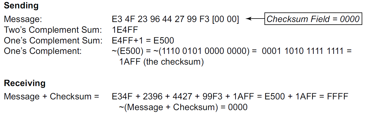
The Internet checksum is a 16-bit mathematical sum used to determine, with reasonably high probability, whether a received message or portion of a message matches the one sent.
Note that the Internet checksum algorithm is not the same as the common cyclic redundancy check (CRC), which offers stronger protection.
To compute the IPv4 header checksum for an outgoing datagram,
-
the value of the datagram’s Checksum field is first set to 0.
-
Then, the 16-bit one’s complement sum of the header is calculated (the entire header is considered a sequence of 16-bit words).
-
The 16-bit one’s complement of this sum is then stored in the Checksum field to make the datagram ready for transmission.
One’s complement addition can be implemented by "end-round-carry addition": when a carry bit is produced using conventional (two’s complement) addition, the carry is added back in as a 1 value.
When an IPv4 datagram is received, a checksum is computed across the whole header, including the value of the Checksum field itself. Assuming there are no errors, the computed checksum value is always 0 (a one’s complement of the value FFFF).
Note that for any nontrivial packet or header, the value of the Checksum field in the packet can never be FFFF.
-
If it were, the sum (prior to the final one’s complement operation at the sender) would have to have been 0.
-
No sum can ever be 0 using one’s complement addition unless all the bytes are 0—something that never happens with any legitimate IPv4 header.
When the header is found to be bad (the computed checksum is nonzero), the IPv4 implementation discards the received datagram.
-
No error message is generated.
-
It is up to the higher layers to somehow detect the missing datagram and retransmit if necessary.
45 10 01 48 00 00 00 00 10 11 70 c4 c0 a8 5b fe c0 a8 5b 82

| 45 10 | Version, IHL, DS, ECN  | 0100 0101 0001 0000

| 01 48 | Total Length           | 0000 0001 0100 1000
                                => 0100 0110 0101 1000
| 00 00 | Identification         | 0000 0000 0000 0000
                                => 0100 0110 0101 1000
| 00 00 | Flags, Fragment Offset | 0000 0000 0000 0000
                                => 0100 0110 0101 1000
| 10 11 | TTL, Protocol          | 0001 0000 0001 0001
                                => 0101 0110 0110 1001
| 70 c4 | Checksum               | 0111 0000 1100 0100
                                => 0101 0110 0110 1001
| c0 a8 | Source Address         | 1100 0000 1010 1000
                                 1 0001 0111 0001 0001
                                 +                   1
                                => 0001 0111 0001 0010 # round-carry
| 5b fe | Source Address         | 0101 1011 1111 1110
                                => 0111 0011 0001 0000
| c0 a8 | Destination Address    | 1100 0000 1010 1000
                                => 0011 0011 1011 1001 # round-carry
| 5b 82 | Destination Address    | 0101 1011 1000 0010
                                => 1000 1111 0011 1011
                                => 0111 0000 1100 0100 # one's complement (i.e. checksum)
                                => 1111 1111 1111 1111 # computed including the Checksum field
                                => 0000 0000 0000 0000 # one's complement (correct)
2. IP Forwarding
Conceptually, IP forwarding is simple, especially for a host.
-
If the destination is directly connected to the host (e.g., a point-to-point link) or on a shared network (e.g., Ethernet), the IP datagram is sent directly to the destination—a router is not required or used.
-
Otherwise, the host sends the datagram to a single router (called the default router) and lets the router deliver the datagram to its destination.
What differentiates a host from a router to IP is how IP datagrams are handled: a host never forwards datagrams it does not originate, whereas routers do.
In our general scheme, the IP protocol can receive a datagram either
-
from another protocol on the same machine (TCP, UDP, etc.)
-
or from a network interface.
The IP layer has some information in memory, usually called a routing table or forwarding table, which it searches each time it receives a datagram to send.
When a datagram is received from a network interface, IP first checks if the destination IP address is one of
-
its own IP addresses (i.e., one of the IP addresses associated with one of its network interfaces)
-
or some other address for which it should receive traffic such as an IP broadcast or multicast address.
If so, the datagram is delivered to the protocol module specified by the Protocol field in the IPv4 header or Next Header field in the IPv6 header.
If the datagram is not destined for one of the IP addresses being used locally by the IP module, then
-
(1) if the IP layer was configured to act as a router, the datagram is forwarded;
-
or (2) the datagram is silently discarded.
-
Under some circumstances (e.g., no route is known in case 1), an ICMP message may be sent back to the source indicating an error condition.
-
2.1. Forwarding Table
The IP protocol standards do not dictate the precise data required to be in a forwarding table, as this choice is left up to the implementer of the IP protocol.
Nevertheless, several key pieces of information are generally required to implement the forwarding table for IP.
-
Destination: This contains a 32-bit field (or 128-bit field for IPv6) used for matching the result of a masking operation.
The destination can be as simple as zero, for a default route covering all destinations, or as long as the full length of an IP address, in the case of a host route that describes only a single destination.
-
Mask: This contains a 32-bit field (128-bit field for IPv6) applied as a bitwise AND mask to the destination IP address of a datagram being looked up in the forwarding table.
The masked result is compared with the set of destinations in the forwarding table entries.
-
Next-hop: This contains the 32-bit IPv4 address or 128-bit IPv6 address of the next IP entity (router or host) to which the datagram should be sent.
The next-hop entity is typically on a network shared with the system performing the forwarding lookup, meaning the two share the same network prefix.
-
Interface: This contains an identifier used by the IP layer to reference the network interface that should be used to send the datagram to its next hop.
For example, it could refer to a host’s 802.11 wireless interface, a wired Ethernet interface, or a PPP interface associated with a serial port.
If the forwarding system is also the sender of the IP datagram, this field is used in selecting which source IP address to use on the outgoing datagram.
$ ip r
default via 192.168.91.2 dev ens32 onlink
172.17.0.0/16 dev docker0 proto kernel scope link src 172.17.0.1 linkdown
192.168.91.0/24 dev ens32 proto kernel scope link src 192.168.91.128
192.168.91.0/24 dev ens34 proto kernel scope link src 192.168.91.138

$ sudo route -n
Kernel IP routing table
Destination     Gateway         Genmask         Flags Metric Ref    Use Iface
0.0.0.0         192.168.91.2    0.0.0.0         UG    0      0        0 ens32
172.17.0.0      0.0.0.0         255.255.0.0     U     0      0        0 docker0
192.168.91.0    0.0.0.0         255.255.255.0   U     0      0        0 ens32
192.168.91.0    0.0.0.0         255.255.255.0   U     0      0        0 ens34
PS C:\> route print -4 =========================================================================== Interface List 10...48 2a e3 94 1e 19 ......Intel(R) Ethernet Connection (10) I219-V 6...02 00 4c 4f 4f 50 ......Microsoft KM-TEST Loopback Adapter 5...8c c6 81 fe 82 c5 ......Microsoft Wi-Fi Direct Virtual Adapter 8...8e c6 81 fe 82 c4 ......Microsoft Wi-Fi Direct Virtual Adapter #2 19...00 50 56 c0 00 01 ......VMware Virtual Ethernet Adapter for VMnet1 9...00 50 56 c0 00 08 ......VMware Virtual Ethernet Adapter for VMnet8 13...8c c6 81 fe 82 c4 ......Intel(R) Wireless-AC 9560 160MHz 1...........................Software Loopback Interface 1 =========================================================================== IPv4 Route Table =========================================================================== Network Destination Netmask Gateway Interface Metric 0.0.0.0 0.0.0.0 10.170.109.254 10.170.109.10 35 10.170.108.0 255.255.254.0 On-link 10.170.109.10 291 10.170.109.10 255.255.255.255 On-link 10.170.109.10 291 10.170.109.255 255.255.255.255 On-link 10.170.109.10 291 127.0.0.0 255.0.0.0 On-link 127.0.0.1 331 127.0.0.1 255.255.255.255 On-link 127.0.0.1 331 127.255.255.255 255.255.255.255 On-link 127.0.0.1 331 169.254.0.0 255.255.0.0 On-link 169.254.24.54 281 169.254.24.54 255.255.255.255 On-link 169.254.24.54 281 169.254.255.255 255.255.255.255 On-link 169.254.24.54 281 192.168.56.0 255.255.255.0 On-link 192.168.56.1 291 192.168.56.1 255.255.255.255 On-link 192.168.56.1 291 192.168.56.255 255.255.255.255 On-link 192.168.56.1 291 192.168.91.0 255.255.255.0 On-link 192.168.91.1 291 192.168.91.1 255.255.255.255 On-link 192.168.91.1 291 192.168.91.255 255.255.255.255 On-link 192.168.91.1 291 224.0.0.0 240.0.0.0 On-link 127.0.0.1 331 224.0.0.0 240.0.0.0 On-link 192.168.56.1 291 224.0.0.0 240.0.0.0 On-link 192.168.91.1 291 224.0.0.0 240.0.0.0 On-link 169.254.24.54 281 224.0.0.0 240.0.0.0 On-link 10.170.109.10 291 255.255.255.255 255.255.255.255 On-link 127.0.0.1 331 255.255.255.255 255.255.255.255 On-link 192.168.56.1 291 255.255.255.255 255.255.255.255 On-link 192.168.91.1 291 255.255.255.255 255.255.255.255 On-link 169.254.24.54 281 255.255.255.255 255.255.255.255 On-link 10.170.109.10 291 =========================================================================== Persistent Routes: None
IP forwarding is performed on a hop-by-hop basis.
-
The routers and hosts do not contain the complete forwarding path to any destination.
-
IP forwarding provides the IP address of only the next-hop entity to which the datagram is sent.
-
It is assumed that the next hop is really closer to the destination than the forwarding system is, and that the next-hop router is directly connected to (i.e., shares a common network prefix with) the forwarding system.
-
It is also generally assumed that no loops are constructed between the next hops so that a datagram does not circulate around the network until its TTL or hop limit expires.
2.2. IP Forwarding Actions
When the IP layer in a host or router needs to send an IP datagram to a next-hop router or host, it first examines the destination IP address (D) in the datagram.
Using the value D, the following longest prefix match algorithm is executed on the forwarding table:
-
Search the table for all entries for which the following property holds: (D ^ mj) = dj,
where mj is the value of the mask field associated with the forwarding entry ej having index j,
and dj is the value of the destination field associated with ej.
If the destination IP address D is bitwise ANDed with the mask in each forwarding table entry (mj),
and the result is compared against the destination in the same forwarding table entry (dj),
the entry (ej here) is a match for the destination IP address.
When a match happens, the algorithm notes the entry index (j here) and how many bits in the mask mj were set to 1, and the more bits set to 1, the better the match.
-
The best matching entry ek (i.e., the one with the largest number of 1 bits in its mask mk) is selected, and its next-hop field nk is used as the next-hop IP address in forwarding the datagram.
If no matches in the forwarding table are found, the datagram is undeliverable.
-
If the undeliverable datagram was generated locally (on this host), a host unreachable error is normally returned to the application that generated the datagram.
-
On a router, an ICMP message is normally sent back to the host that sent the datagram.
In some circumstances, more than one entry may match an equal number of 1 bits.
-
This can happen, for example, when more than one default route is available (e.g., when attached to more than one ISP, called multihoming).
-
The end-system behavior in such cases is not set by standards and is instead specific to the operating system’s protocol implementation.
-
A common behavior is for the system to simply choose the first match.
-
More sophisticated systems may attempt to load-balance or split traffic across the multiple routes.
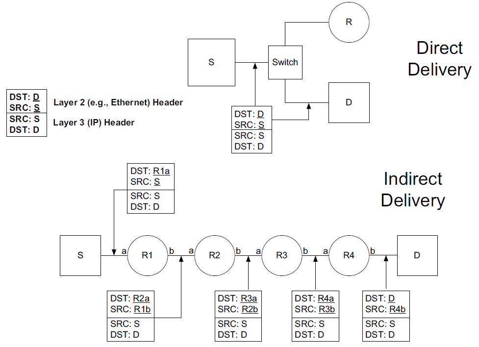
2.3. Direct delivery and indirect delivery
Where all systems are using the same network prefix, is called direct delivery, and the other case is called indirect delivery.
-
Direct delivery does not require the presence of a router—IP datagrams are encapsulated in a link-layer frame that directly identifies the source and destination.
-
Indirect delivery involves a router—data is forwarded to the router using the router’s link-layer address as the destination link-layer address.
-
The router’s IP address does not appear in the IP datagram (unless the router itself is the source or destination, or when source routing is used).
In the following table, the destination IPv4 address D (10.0.0.9) matches both the first and second forwarding table entries.
-
Because it matches the second entry better (25 bits instead of none), the gateway or next-hop address is 10.0.0.100, the address S.
-
Thus, the gateway portion of the entry contains the address of the sending host’s own network interface (no router is referenced), indicating that direct delivery is to be used to send the datagram.
| Destination | Mask | Gateway (Next Hop) | Interface |
|---|---|---|---|
0.0.0.0 |
0.0.0.0 |
10.0.0.1 |
10.0.0.100 |
10.0.0.0 |
255.255.255.128 |
10.0.0.100 |
10.0.0.100 |
-
Host S is configured with IPv4 address and subnet mask 10.0.0.100/25.
-
Datagrams destined for addresses in the range 10.0.0.1 through 10.0.0.126 use the second forwarding table entry and are sent using direct delivery.
-
All other datagrams use the first entry and are given to router R with IPv4 address 10.0.0.1.
The datagram is encapsulated in a lower-layer frame destined for the target host D.
-
If the lower-layer address of the target host is unknown, the ARP protocol (for IPv4) or Neighbor Solicitation (for IPv6) operation may be invoked at this point to determine the correct lower-layer address, D.
-
Once known, the destination address in the datagram is D's IPv4 address (10.0.0.9), and D is placed in the Destination IP Address field in the lower-layer header.
-
The switch delivers the frame to D based solely on the link-layer address D; it pays no attention to the IP addresses.
$ ip n
172.17.0.2 dev docker0 lladdr 02:42:ac:11:00:02 STALE
192.168.91.254 dev ens32 lladdr 00:50:56:fc:89:96 STALE
192.168.91.1 dev ens32 lladdr 00:50:56:c0:00:08 REACHABLE
192.168.91.2 dev ens34 lladdr 00:50:56:e9:f6:27 STALE
192.168.91.2 dev ens32 lladdr 00:50:56:e9:f6:27 STALE
192.168.91.138 dev ens32  FAILED
fe80::50c2:d6ef:87fb:1b7b dev ens34 lladdr 00:50:56:c0:00:08 STALE

$ sudo arp -n
Address                  HWtype  HWaddress           Flags Mask            Iface
172.17.0.2               ether   02:42:ac:11:00:02   C                     docker0
192.168.91.254           ether   00:50:56:fc:89:96   C                     ens32
192.168.91.1             ether   00:50:56:c0:00:08   C                     ens32
192.168.91.2             ether   00:50:56:e9:f6:27   C                     ens34
192.168.91.2             ether   00:50:56:e9:f6:27   C                     ens32
192.168.91.138                   (incomplete)                              ens32
| Destination | Mask | Gateway (Next Hop) | Interface | Note |
|---|---|---|---|---|
0.0.0.0 |
0.0.0.0 |
70.231.159.254 |
70.231.132.85 |
NAT |
10.0.0.0 |
255.255.255.128 |
10.0.0.100 |
10.0.0.1 |
NAT |
-
The forwarding table at R1 indicates that address translation should be performed for traffic.
-
The router has a private address on one side (10.0.0.1) and a public address on the other (70.231.132.85).
-
Address translation is used to make datagrams originating on the 10.0.0.0/25 network appear to the Internet as though they had been sent from 70.231.132.85.
node-0:~$ ip r
default via 192.168.91.2 dev ens32 onlink
192.168.91.0/24 dev ens32 proto kernel scope link src 192.168.91.128
192.168.91.0/24 dev ens34 proto kernel scope link src 192.168.91.138

node-0:~$ sudo ip r del default

node-0:~$ sudo ip r add default via 192.168.91.137 dev ens32

node-0:~$ ip r
default via 192.168.91.137 dev ens32
192.168.91.0/24 dev ens32 proto kernel scope link src 192.168.91.128
192.168.91.0/24 dev ens34 proto kernel scope link src 192.168.91.138
node-1:~$ ip r
default via 192.168.91.2 dev ens32
192.168.56.0/24 dev ens36 proto kernel scope link src 192.168.56.128
192.168.91.0/24 dev ens32 proto kernel scope link src 192.168.91.137
192.168.91.0/24 dev ens34 proto kernel scope link src 192.168.91.131
192.168.91.0/24 dev ens33 proto kernel scope link src 192.168.91.129
node-1:~$ sudo sysctl net.ipv4.ip_forward=1
net.ipv4.ip_forward = 1PS C:\> ipconfig
Wireless LAN adapter Wi-Fi:
Connection-specific DNS Suffix . : xxxxxxxxx
Link-local IPv6 Address . . . . . : fe80::20b2:4f30:ed18:5956%13
IPv4 Address. . . . . . . . . . . : 10.170.109.10
Subnet Mask . . . . . . . . . . . : 255.255.254.0
Default Gateway . . . . . . . . . : 10.170.109.254node-0:~$ sudo traceroute -I 10.170.109.10
traceroute to 10.170.109.10 (10.170.109.10), 30 hops max, 60 byte packets
1 node-1 (192.168.91.137) 0.256 ms 0.223 ms 0.252 ms
2 192.168.91.2 (192.168.91.2) 0.269 ms 0.256 ms 0.235 ms
3 10.170.109.10 (10.170.109.10) 0.727 ms 0.871 ms 1.175 ms3. Mobile IP
Mobile IP is based on the idea that a host has a home network but may visit other networks from time to time.
-
While at home, ordinary forwarding is performed.
-
When away from home, the host keeps the IP address it would ordinarily use at home, but some special routing and forwarding tricks are used to make the host appear to the network, and to the other systems with which it communicates, as though it is attached to its home network.
The scheme depends on a special type of router called a home agent that helps provide routing for mobile nodes.
Most of the complexity in MIPv6 involves signaling messages and how they are secured. These messages use various forms of the Mobility extension header (Next Header field value 135, often just called the mobility header), so Mobile IP is, in effect, a special protocol of its own.
3.1. The Basic Model for IP Mobility: Bidirectional Tunneling
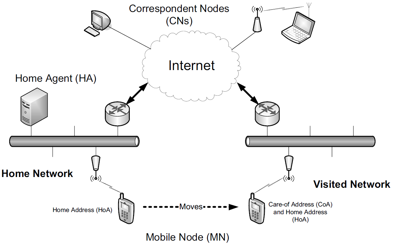
The following figure shows the entities involved in making MIPv6 work. Much of the terminology also applies to MIPv4 [RFC5944].
-
A host that might move is called a mobile node (MN), and the hosts with which it is communicating are called correspondent nodes (CNs).
-
The MN is given an IP address chosen from the network prefix used in its home network. This address is known as its home address (HoA).
When it travels to a visited network, it is given an additional address, called its care-of-address (CoA).
-
In the basic model, whenever a CN communicates with an MN, the traffic is routed through the MN’s home agent (HA).
HAs are a special type of router deployed in the network infrastructure like other important systems (e.g., routers and Web servers).
-
The association between an MN’s HoA and its CoA is called a binding for the MN.
The basic model works in cases where an MN’s CNs do not engage in the MIPv6 protocol. This model is also used for network mobility (called NEMO [RFC3963]), when an entire network is mobile.
-
When the MN (or mobile network router) attaches to a new point in the network, it receives its CoA and sends a binding update message to its HA. The HA responds with a binding acknowledgment.
-
Assuming that all goes well, traffic between the MN and CNs is thereafter routed through the MN’s HA using a two-way form of IPv6 packet tunneling[RFC2473] called bidirectional tunneling.
These messages are ordinarily protected using IPsec with the Encapsulating Security Payload (ESP).
Doing so ensures that an HA is not fooled into accepting a binding update from a fake MN.
4. Host Processing of IP Datagrams
Although routers do not ordinarily have to consider which IP addresses to place in the Source IP Address and Destination IP Address fields of the packets they forward, hosts must consider both.
-
Applications such as Web browsers may attempt to make connections to a named host or server that can have multiple addresses.
-
The client system making such connections may also have multiple addresses.
4.1. Host Models
Although it may appear to be a straightforward decision to determine whether a received unicast datagram matches one of a host’s IP addresses and should be processed, this decision depends on the host model of the receiving system [RFC1122] and is most relevant for multihomed hosts.
There are two host models, the strong host model and the weak host model.
-
In the strong host model, a datagram is accepted for delivery to the local protocol stack only if the IP address contained in the Destination IP Address field matches one of those configured on the interface upon which the datagram arrived.
-
In systems implementing the weak host model, the opposite is true—a datagram carrying a destination address matching any of the local addresses may arrive on any interface and is processed by the receiving protocol stack, irrespective of the network interface upon which it arrived.
Host models also apply to sending behavior. That is, a host using the strong host model sends datagrams from a particular interface only if one of the interface’s configured addresses matches the Source IP Address field in the datagram being sent.
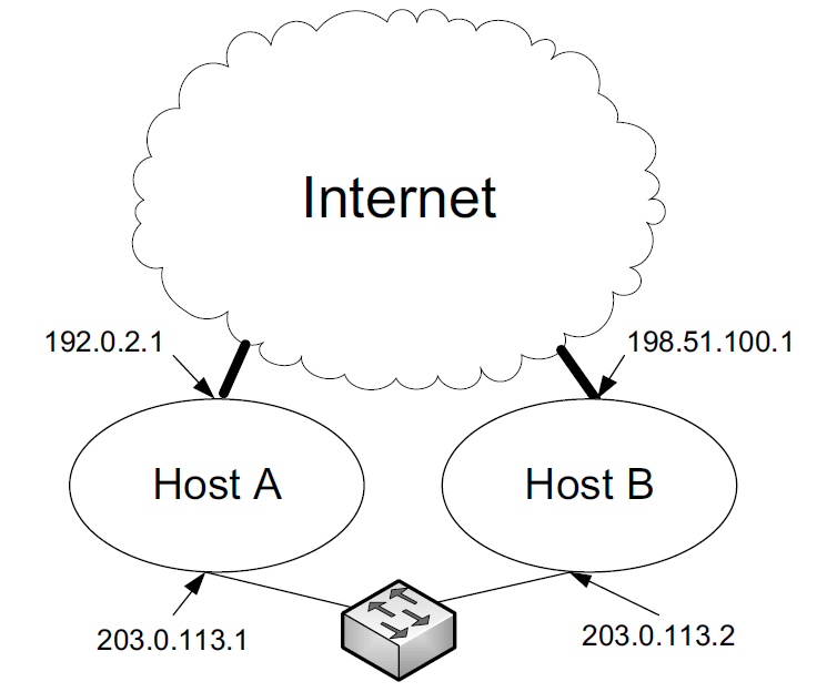
-
In this example, two hosts (A and B) are connected through the global Internet but also through a local network.
-
If host A is set up to conform to the strong host model, packets it receives destined for 203.0.113.1 from the Internet or destined for 192.0.2.1 from the local network are dropped.
-
This situation can arise, for example, if host B is configured to obey the weak host model.
-
It may choose to send packets to 192.0.2.1 using the local network (e.g., because doing so may be cheaper or faster).
-
This situation seems unfortunate, as A receives what appear to be perfectly legitimate packets, yet drops them merely because it is operating according to the strong host model.
-
The host model, for both sending and receiving behavior, can be configured in some operating systems.
-
In Windows (Vista and later), strong host behavior is the default for sending and receiving for IPv4 and IPv6.
-
In Linux, the IP behavior defaults to the weak host model.
-
BSD (including Mac OS X) uses the strong hostmodel.
In Windows, the following commands can be used to configure weak host receive and send behavior, respectively:
C:\> netsh interface ipvX set interface <ifname> weakhostreceive=Yabled
C:\> netsh interface ipvX set interface <ifname> weakhostsend=Yabled
For these commands, <ifname> is replaced with the appropriate interface name; X is replaced with either 4 or 6, depending on which version of IP is being configured; and Y is replaced with either en or dis, depending on whether weak behavior is to be enabled or disabled, respectively.
netsh interface ipv4>show interfaces

Idx     Met         MTU          State                Name
---  ----------  ----------  ------------  ---------------------------
  1          75  4294967295  connected     Loopback Pseudo-Interface 1
 13          35        1500  connected     Wi-Fi
 10           5        1500  disconnected  Ethernet

netsh interface ipv4>show interfaces interface="Wi-Fi"

Interface Wi-Fi Parameters
----------------------------------------------
Weak Host Sends                    : disabled
Weak Host Receives                 : disabled
References
-
[1] Kevin Fall, W. Stevens TCP/IP Illustrated: The Protocols, Volume 1. 2nd edition, Addison-Wesley Professional, 2011
-
[AN] https://www.iana.org/assignments/protocol-numbers/protocol-numbers.xhtml