TCP/IP: Broadcasting and Local Multicasting (IGMP and MLD)
There are four kinds of IP addresses: unicast, anycast, multicast, and broadcast.
At the present time, multicast is used more in enterprise and local networks than in the wide area.
Broadcasting and multicasting provide two services for an application: delivery of packets to multiple destinations, and solicitation/discovery of servers by clients.
-
Delivery to multiple destinations
There are many applications that deliver information to multiple recipients: interactive conferencing and dissemination of mail or news to multiple recipients, for example.
Without broadcasting or multicasting, these types of services tend to use TCP today (delivering a separate copy to each destination, which can be very inefficient).
-
Solicitation of servers by clients
Using broadcasting or multicasting, an application can send a request for a server without knowing any particular server’s IP address.
A laptop, for example, might need to get its initial IP address and find its nearest router using DHCP when little is known about the local networking environment.
Although both broadcasting and multicasting can provide these important capabilities,
-
multicasting is generally preferable to broadcasting because multicasting involves only those systems that support or use a particular service or protocol, and broadcasting does not.
-
Thus, a broadcast request affects all hosts that are reachable within the scope of the broadcast, whereas multicast affects only those hosts that are likely to be interested in the request.
Broadcasting has been supported by the IPv4 protocol since its inception, and multicast was added with the publication of [RFC1112].
IPv6 supports multicasting but does not support broadcasting.
Generally, only user applications that use the
-
UDP transport protocol take advantage of broadcasting and multicasting, where it makes sense for an application to send a single message to multiple recipients.
-
TCP is a connection-oriented protocol that implies a connection between two hosts (specified by IP addresses) and one process on each host (specified by port numbers).
TCP can use unicast and anycast addresses (recall that anycast addresses behave like unicast addresses), but not broadcast or multicast addresses.
Broadcasting and multicasting are also used by important system processes such as routing protocols, ARP, ND in IPv6, and others.
Multicasting is an important but arguably optional feature in IPv4, but it is mandatory in IPv6 because of its use in ND, a service critical even to unicast communication.
1. Broadcasting
Broadcasting refers to sending a message to all possible receivers in a network.
In principle, this is simple: a router simply forwards a copy of any message it receives out of every interface other than the one on which the message arrived.
Consider a set of hosts on a network such as an Ethernet that supports broadcasting at the link layer.
-
Each Ethernet frame contains the source and destination MAC addresses (48-bit values).
-
Normally, each IP packet is destined for a single host, so unicast addressing is used and the destination’s unique MAC address is determined using ARP or IPv6 ND.
When a frame is sent to a unicast destination in this way, communication between any two hosts does not bother any of the remaining hosts on the network.
For switched Ethernet networks, these are the types of addresses found in the station caches in switches and bridges.
-
There are times, however, when a host wants to send a frame to every other host on the network (or VLAN)—this is called a broadcast.
1.1. Using Broadcast Addresses
On an Ethernet or similar network, a multicast MAC address has the low-order bit of the high-order byte turned on.
-
In hexadecimal this looks like 01:00:00:00:00:00.
-
We may consider the Ethernet broadcast address ff:ff:ff:ff:ff:ff as a special case of the Ethernet multicast address.
Recall that in IPv4, each subnet has
-
a local subnet-directed broadcast address formed by placing all 1 bits in the host portion of the address,
-
and the special address 255.255.255.255 corresponds to a local network (also called limited) broadcast.
|
Directed broadcasts are routable in principle but won’t be forwarded by default. Limited broadcasts are generally not routable and won’t be forwarded. |
node-0:~$ ip a show ens32
2: ens32: <BROADCAST,MULTICAST,UP,LOWER_UP> mtu 2000 qdisc pfifo_fast state UP group default qlen 1000
    link/ether 00:0c:29:8c:df:3f brd ff:ff:ff:ff:ff:ff
    altname enp2s0
    inet 192.168.91.128/24 brd 192.168.91.255 scope global ens32
       valid_lft forever preferred_lft forever
Here, the address 192.168.91.255 is the (subnet-directed) broadcast address used on the network to which device ens32 is attached.
-
This address is formed by taking the network prefix (192.168.91.0/24) and combining it with 32 – 24 = 8 bits of 1s in the host portion of the address: 192.168.91.0 OR 0.0.0.255 = 192.68.91.255.
-
A simple utility called ipcalc or ipcalc-ng is available on some systems to perform this calculation.
node-0:~$ ipcalc 192.168.91.128/24
Address:   192.168.91.128       11000000.10101000.01011011. 10000000
Netmask:   255.255.255.0 = 24   11111111.11111111.11111111. 00000000
Wildcard:  0.0.0.255            00000000.00000000.00000000. 11111111
=>
Network:   192.168.91.0/24      11000000.10101000.01011011. 00000000
HostMin:   192.168.91.1         11000000.10101000.01011011. 00000001
HostMax:   192.168.91.254       11000000.10101000.01011011. 11111110
Broadcast: 192.168.91.255       11000000.10101000.01011011. 11111111
Hosts/Net: 254                   Class C, Private Internet

node-0:~$ ipcalc-ng fe80::20c:29ff:fe8c:df3f/64
Full Address:	fe80:0000:0000:0000:020c:29ff:fe8c:df3f
Address:	fe80::20c:29ff:fe8c:df3f
Full Network:	fe80:0000:0000:0000:0000:0000:0000:0000/64
Network:	fe80::/64
Netmask:	ffff:ffff:ffff:ffff:: = 64

Address space:	Link-Scoped Unicast
HostMin:	fe80::
HostMax:	fe80::ffff:ffff:ffff:ffff
Hosts/Net:	2^(64) = 18446744073709551616
node-1:~$ ip a show ens32
2: ens32: <BROADCAST,MULTICAST,UP,LOWER_UP> mtu 1500 qdisc pfifo_fast state UP group default qlen 1000
    link/ether 00:0c:29:85:26:10 brd ff:ff:ff:ff:ff:ff
    inet 192.168.91.137/24 brd 192.168.91.255 scope global ens32
       valid_lft forever preferred_lft forever

// If this value is nonzero, Linux will ignore all ICMP_ECHO packets sent to broadcast addresses.
node-1:~$ sudo sysctl net.ipv4.icmp_echo_ignore_broadcasts=0
net.ipv4.icmp_echo_ignore_broadcasts = 0
node-0:~$ ping -c 1 -b 192.168.91.255
PING 192.168.91.255 (192.168.91.255) 56(84) bytes of data.
64 bytes from 192.168.91.128: icmp_seq=1 ttl=64 time=0.016 msnode-0:~$ sudo tcpdump -en icmp
10:02:47.802057 00:0c:29:8c:df:3f > ff:ff:ff:ff:ff:ff, ethertype IPv4 (0x0800), length 98: 192.168.91.128 > 192.168.91.255: ICMP echo request, id 33826, seq 1, length 64
10:02:47.802164 00:50:56:e9:f6:27 > 00:0c:29:8c:df:49, ethertype IPv4 (0x0800), length 98: 192.168.91.2 > 192.168.91.128: ICMP echo reply, id 33826, seq 1, length 64
10:02:47.802408 00:0c:29:85:26:10 > 00:0c:29:8c:df:3f, ethertype IPv4 (0x0800), length 98: 192.168.91.137 > 192.168.91.128: ICMP echo reply, id 33826, seq 1, length 64
-
An ICMPv4 Echo Request message sent to the directed broadcast address on the local subnetwork is encapsulated in a link-layer broadcast frame with a destination address of all 1s.
-
The source addresses at both the IP and link layers are entirely conventional unicast; multicast addresses are used only as destination addresses.
2. Multicasting
To reduce the amount of overhead involved in broadcasting, it is possible to send traffic only to those receivers that are interested in it. This is called multicasting.
Fundamentally, this is accomplished by either having the sender indicate the receivers, or instead having the receivers independently indicate their interest. The network then becomes responsible for sending traffic only to intended/interested recipients.
Implementing multicast is considerably more challenging than broadcast because multicast state (information) must be maintained by hosts and routers as to what traffic is of interest to what receivers.
-
In the TCP/IP model of multicasting, receivers indicate their interest in what traffic they wish to receive by specifying a multicast address and optional list of sources.
This information is maintained as soft state within hosts and routers, meaning that it must be updated regularly or it will time out and be deleted.
When this happens, delivery of multicast traffic either ceases or reverts to broadcast.
ASM (any-source multicast)
-
IP multicasting originated using a design based on the way group addressing works in link-layer networks such as Ethernet.
Each station selects the group address for which it is willing to accept traffic, also sometimes called any-source multicast (ASM) because of the insensitivity to the identity of the sender.
SSM (source-specific multicast)
-
An alternative form that is sensitive to the identity of the sender called source-specific multicast (SSM) [RFC4607] that allows end stations to explicitly include or exclude traffic sent to a multicast group from a particular set of senders.
2.1. Converting IP Multicast Addresses to 802 MAC/Ethernet Addresses
When using unicast addresses on Ethernet-like networks, ARP is usually used to determine a local destination’s MAC address given its IPv4 address. In IPv6, ND serves a similar role.
When we looked at broadcasting earlier, we noticed that there is a single well-known broadcast MAC address that can always be used to reach all stations on a LAN or VLAN.
What destination MAC address should be placed in a link-layer frame when we wish to send multicast traffic?
To carry IP multicast efficiently on a link-layer on IEEE 802 networks, there should be a one-to-one mapping between packets and addresses at the IP layer and frames at the link layer.
-
The IANA owns the IEEE Organizationally Unique Identifier (abbreviated OUI, or more informally Ethernet address prefix) 00:00:5e.
With it, IANA is given the right to use group (multicast) MAC addresses starting with 01:00:5e as well as unicast addresses starting with 00:00:5e.
This prefix is used as the high-order 24 bits of the Ethernet address, meaning that this block includes unicast addresses in the range 00:00:5e:00:00:00 through 00:00:5e:ff:ff:ff and group addresses in the range 01:00:5e:00:00:00 through 01:00:5e:ff:ff:ff.
-
Other organizations besides IANA own address blocks as well, but only IANA devotes some of its space to support of IP multicasting.
The IANA allocates half of its group block to identifying IPv4 multicast traffic on IEEE 802 LANs, which means that the Ethernet addresses corresponding to IPv4 multicasting are in the range 01:00:5e:00:00:00 through 01:00:5e:7f:ff:ff.
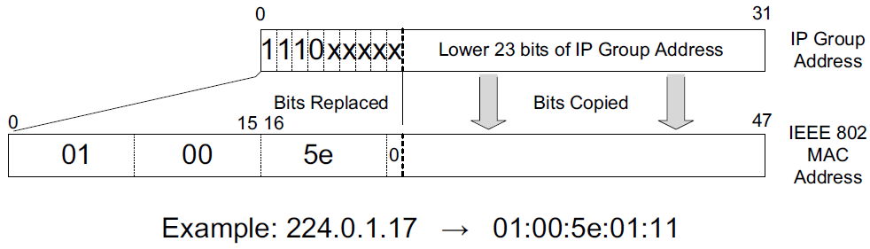
Example: 224.0.0.17 (11100000.000-00000.00000000.00010001) → 01:00:5e:01:11
IPv4 multicast addresses are contained within the address space from 224.0.0.0 to 239.255.255.255 (formerly known as class D address space). All such addresses share a common 4-bit sequence of 1110 in the high-order bits.
IP Address: 224.0.0.0 11100000.0-0000000.00000000.00000000
IP Address: 239.255.255.255 11101111.1-1111111.11111111.11111111
MAC Address 00000001.00000000.01011110.0-0000000.00000000.00000000
=>
MAC Address 00000001.00000000.01011110.0-0000000.00000000.00000000
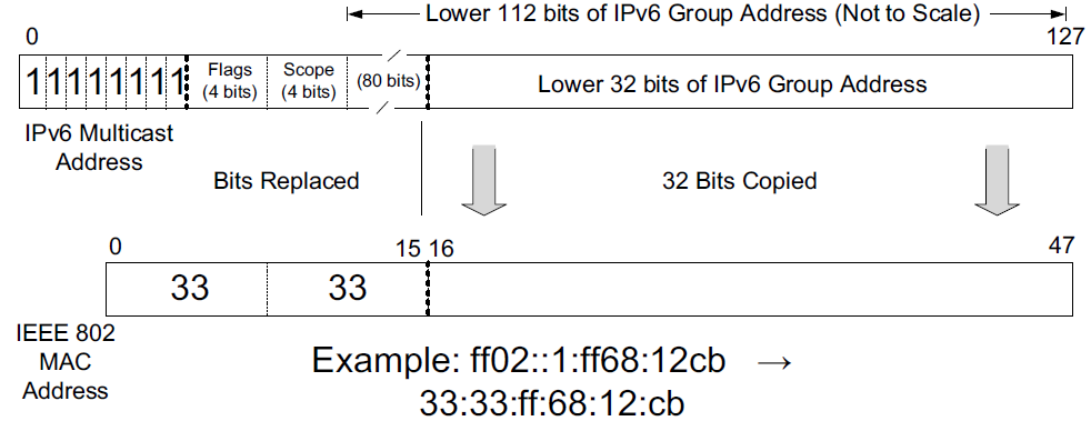
MAC Address 00000001.00000000.01011110.0-1111111.11111111.11111111For IPv6, the 16-bit OUI hexadecimal prefix is 33:33, which means that the last 32 bits of the IPv6 address can be used to form the link-layer address. All IPv6 multicast addresses begin with ff, and the subsequent 8 bits are used for flags and scope information, this leaves 128 – 16 = 112 bits for representing groups.
-
ICMPv4 echo request to those hosts that respond to the Multicast DNS (mDNS) address 224.0.0.251.
node-1:~$ ping -c 1 224.0.0.251
PING 224.0.0.251 (224.0.0.251) 56(84) bytes of data.
64 bytes from 192.168.91.128: icmp_seq=1 ttl=64 time=0.187 ms

--- 224.0.0.251 ping statistics ---
1 packets transmitted, 1 received, 0% packet loss, time 0ms
rtt min/avg/max/mdev = 0.187/0.187/0.187/0.000 ms
node-0:~$ sudo tcpdump -ten icmp 00:0c:29:85:26:10 > 01:00:5e:00:00:fb, ethertype IPv4 (0x0800), length 98: 192.168.91.137 > 224.0.0.251: ICMP echo request, id 13338, seq 1, length 64 00:0c:29:8c:df:3f > 00:0c:29:85:26:10, ethertype IPv4 (0x0800), length 98: 192.168.91.128 > 192.168.91.137: ICMP echo reply, id 13338, seq 1, length 64 -
ICMPv6 echo request to those hosts that respond to the Multicast DNS (mDNSv6) address ff02::fb.
node-1:~$ ping -c 1 -I ens32 ff02::fb
PING ff02::fb(ff02::fb) from :: ens32: 56 data bytes
64 bytes from fe80::20c:29ff:fe8c:df3f%ens32: icmp_seq=1 ttl=64 time=0.667 ms

--- ff02::fb ping statistics ---
1 packets transmitted, 1 received, 0% packet loss, time 0ms
rtt min/avg/max/mdev = 0.667/0.667/0.667/0.000 ms
node-0:~$ sudo tcpdump -i ens32 -ten icmp6 00:0c:29:85:26:10 > 33:33:00:00:00:fb, ethertype IPv6 (0x86dd), length 118: fe80::20c:29ff:fe85:2610 > ff02::fb: ICMP6, echo request, id 13361, seq 1, length 64 00:0c:29:8c:df:3f > 00:0c:29:85:26:10, ethertype IPv6 (0x86dd), length 118: fe80::20c:29ff:fe8c:df3f > fe80::20c:29ff:fe85:2610: ICMP6, echo reply, id 13361, seq 1, length 64
2.2. Receiving Multicast Datagrams
Fundamental to multicasting is the concept of a process joining or leaving one or more multicast groups on a given interface on a host.
Membership in a multicast group on a given interface is dynamic—it changes over time as processes join and leave groups.
In addition to joining or leaving groups, additional methods are needed if a process wishes to specify sources it cares to hear from or exclude.
A process can join the same group on multiple interfaces, multiple groups on the same interface, or any combination thereof.
C:\>netsh interface ipv6 show joins

Interface 1: Loopback Pseudo-Interface 1

Scope       References  Last  Address
----------  ----------  ----  ---------------------------------
0                    1  Yes   ff02::c

Interface 13: Wi-Fi

Scope       References  Last  Address
----------  ----------  ----  ---------------------------------
0                    0  Yes   ff01::1
0                    0  Yes   ff02::1
0                    1  Yes   ff02::c
0                    3  Yes   ff02::fb
0                    1  Yes   ff02::1:3
0                    1  Yes   ff02::1:ff18:5956
node-0:~$ ip m
1: lo
inet 224.0.0.251
inet 224.0.0.1
inet6 ff02::fb
inet6 ff02::1
inet6 ff01::1
2: ens32
link 01:00:5e:00:00:01
link 01:00:5e:00:00:fb
link 33:33:00:00:00:01
link 33:33:ff:8c:df:3f
link 33:33:00:00:00:fb
inet 224.0.0.251
inet 224.0.0.1
inet6 ff02::fb
inet6 ff02::1:ff8c:df3f
inet6 ff02::1
inet6 ff01::1224.0.0.251, ff02::fb # mDNS
224.0.0.1, ff02::1 # all hosts/nodes
ff01::1 # all routers on a local network
ff02::1:ff8c:df3f # link-local multicast addressnode-0:~ sudo apt-get install avahi-utilsnode-2:~$ avahi-resolve --name node-0.local -4
node-0.local 192.168.71.40
node-2:~$ avahi-resolve --name node-0.local -6
node-0.local fe80::a00:27ff:fec8:4e0cnode-0:~$ sudo tcpdump -tnv host 224.0.0.251 or host ff02::fb
IP6 (flowlabel 0x5a56e, hlim 255, next-header UDP (17) payload length: 38) fe80::a00:27ff:fe4d:17af.5353 > ff02::fb.5353: [udp sum ok] 0 A (QM)? node-0.local. (30)
IP (tos 0x0, ttl 255, id 51882, offset 0, flags [DF], proto UDP (17), length 58)
192.168.71.54.5353 > 224.0.0.251.5353: 0 A (QM)? node-0.local. (30)
IP (tos 0x0, ttl 255, id 64814, offset 0, flags [DF], proto UDP (17), length 84)
192.168.71.40.5353 > 224.0.0.251.5353: 0*- [0q] 2/0/0 node-0.local. (Cache flush) A 192.168.71.40, node-0.local. (Cache flush) A 192.168.71.53 (56)
IP6 (flowlabel 0x5a56e, hlim 255, next-header UDP (17) payload length: 38) fe80::a00:27ff:fe4d:17af.5353 > ff02::fb.5353: [udp sum ok] 0 AAAA (QM)? node-0.local. (30)
IP6 (flowlabel 0xa0423, hlim 255, next-header UDP (17) payload length: 60) fe80::a00:27ff:fec8:4e0c.5353 > ff02::fb.5353: [bad udp cksum 0x7da0 -> 0x8f7e!] 0*- [0q] 1/0/0 node-0.local. (Cache flush) AAAA fe80::a00:27ff:fec8:4e0c (52)
IP (tos 0x0, ttl 255, id 52548, offset 0, flags [DF], proto UDP (17), length 58)
192.168.71.54.5353 > 224.0.0.251.5353: 0 AAAA (QM)? node-0.local. (30)
IP (tos 0x0, ttl 255, id 65330, offset 0, flags [DF], proto UDP (17), length 80)
192.168.71.40.5353 > 224.0.0.251.5353: 0*- [0q] 1/0/0 node-0.local. (Cache flush) AAAA fe80::a00:27ff:fec8:4e0c (52)2.3. Host Address Filtering
In a typical switched Ethernet environment, broadcast and multicast frames are replicated on all segments within a VLAN, along a spanning tree formed among the switches. Such frames are delivered to the NIC on each host which checks the correctness of the frame (using the CRC) and makes a decision about whether to receive the frame and deliver it to the device driver and network stack.
Normally the NIC receives only those frames whose destination address is either the hardware address of the interface or the broadcast address.
However, when multicast frames are involved, the situation is somewhat more complicated.
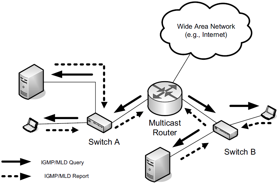
3. The Internet Group Management Protocol (IGMP) and Multicast Listener Discovery Protocol (MLD)
When multicast datagrams are to be forwarded over a wide area network or within an enterprise across multiple subnets, we require that multicast routing be enabled by one or more multicast routers.
Two major protocols are used to allow multicast routers to learn the groups in which nearby hosts are interested:
-
the Internet Group Management Protocol (IGMP) used by IPv4
-
and the Multicast Listener Discovery (MLD) protocol used by IPv6.
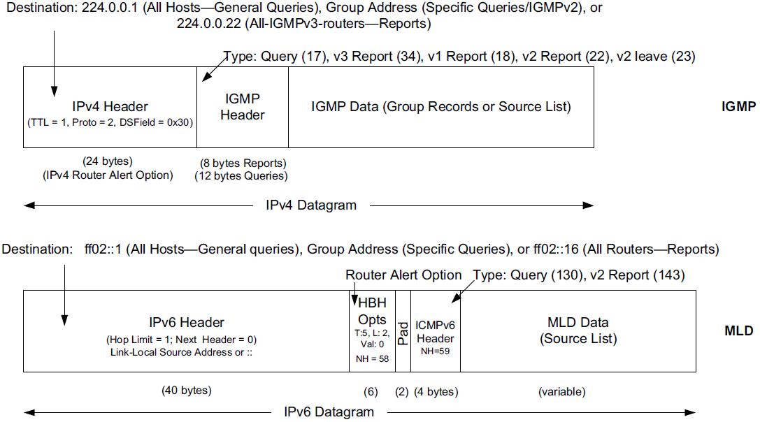
While IGMP is a separate protocol used with IPv4, MLD is really part of ICMPv6.
-
IGMP (MLD) queries are sent by multicast routers to the All Hosts multicast address, 224.0.0.1 (IGMP), or the All Nodes link-scope multicast address, ff02::1 (MLD), and processed by every host implementing IP multicast.
-
Membership report messages are sent by group members (hosts) in response to the queries but may also be sent in an unsolicited way from hosts that wish to inform multicast routers that their group membership(s) and/or interest in particular sources has changed.
-
IGMPv3 reports are sent to the IGMPv3-capable multicast router address 224.0.0.22.
-
MLDv2 reports are sent to the corresponding MLDv2 Listeners IPv6 multicast address ff02::16.
-
-
Note that multicast routers themselves may also act as members when they join multicast groups.