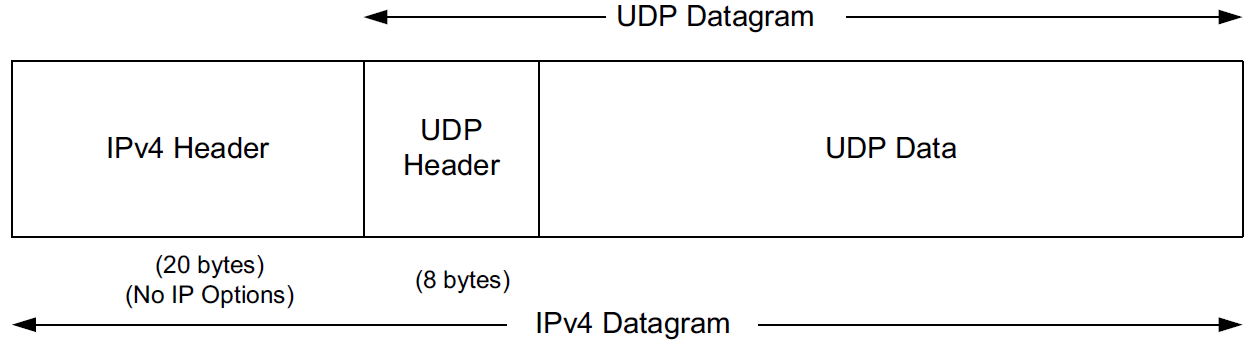
TCP/IP: User Datagram Protocol (UDP) and IP Fragmentation
UDP is a simple, datagram-oriented, transport-layer protocol that preserves message boundaries.
It does not provide error correction, sequencing, duplicate elimination, flow control, or congestion control.
It can provide error detection, and it includes the first true end-to-end checksum at the transport layer that we have encountered.
This protocol provides minimal functionality itself, so applications using it have a great deal of control over how packets are sent and processed.
1. UDP Header
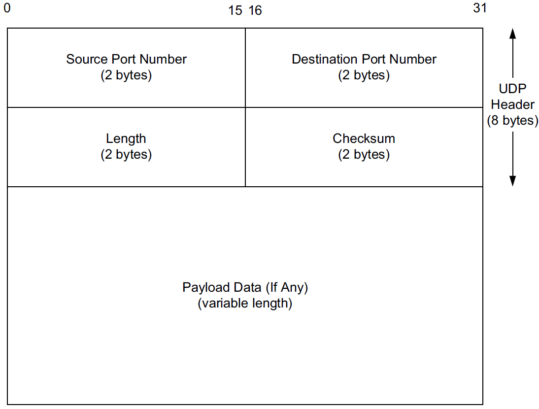
Port numbers act as mailboxes and help a protocol implementation identify the sending and receiving processes. They are purely abstract—they do not correspond to any physical entity on a host.
-
In UDP, port numbers are positive 16-bit numbers, and the source port number is optional; it may be set to 0 if the sender of the datagram never requires a reply.
-
Transport protocols such as TCP, UDP, and SCTP [RFC4960] use the destination port number to help demultiplex incoming data from IP.
-
Because IP demultiplexes the incoming IP datagram to a particular transport protocol based on the value of the Protocol field in the IPv4 header or Next Header field in the IPv6 header, this means that the port numbers can be made independent among the transport protocols.
Despite this independence, if a well-known service is provided (or can conceivably be provided) by both TCP and UDP, the port number is normally allocated to be the same for both transport protocols. This is purely for convenience and is not required by the protocols.
The UDP Length field is the length of the UDP header and the UDP data in bytes. The minimum value for this field is 8 except when UDP is used with IPv6 jumbograms.
|
Note that the UDP Length field is redundant; the IPv4 header contains the datagram’s total length, and the IPv6 header contains the payload length.
In either case, the UDP Length field should match the length computed from the IP-layer information. |
2. UDP Checksum
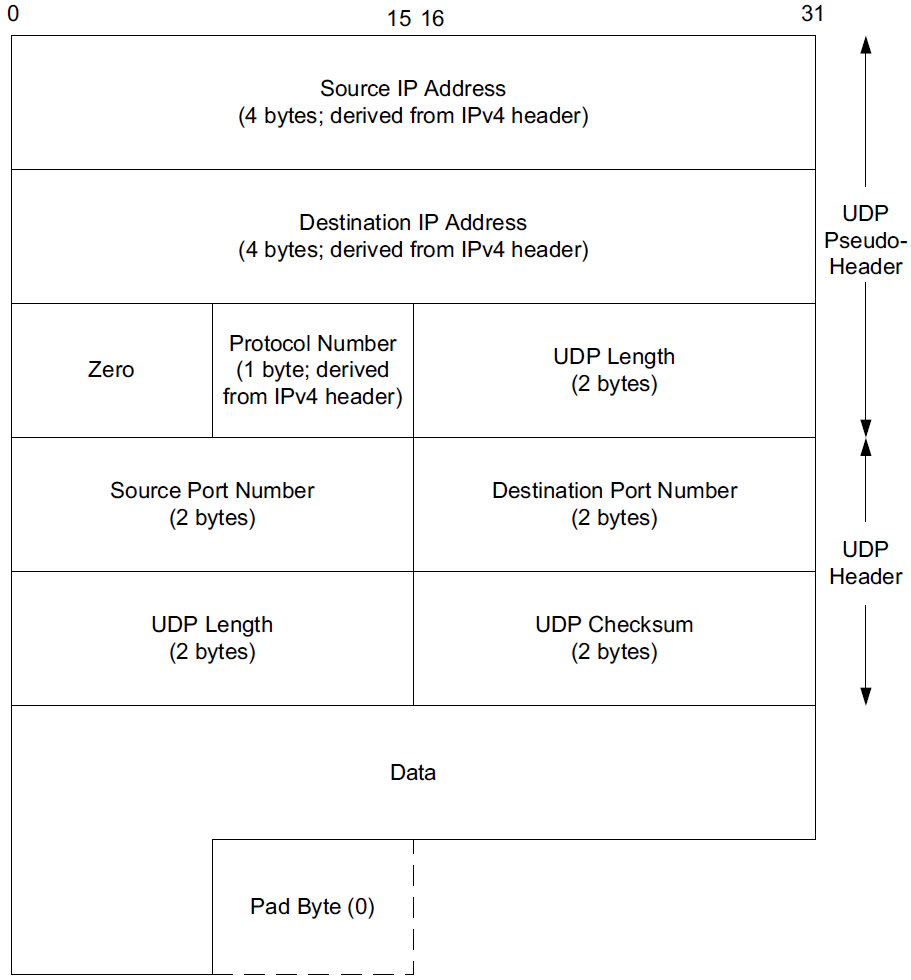
The UDP checksum is the first end-to-end transport-layer checksum we have encountered (ICMP has an end-to-end checksum but is not a true transport protocol). It covers the UDP header, the UDP data, and a pseudo-header.
It is computed at the initial sender and checked at the final destination. It is not modified in transit (except when it passes through a NAT).
Recall that the checksum in the IPv4 header covers only the header (i.e.,
-
it does not cover any data in the IP packet)
-
and is recomputed at each IP hop (required because the IPv4 TTL field is decremented by routers when the datagram is forwarded).
Transport protocols (e.g., TCP, UDP) use checksums to cover their headers and data.
-
With UDP, the checksum is optional (although strongly suggested), while with the others it is mandatory.
-
When UDP is used with IPv6, computation and use of the checksum are mandatory because there is no header checksum at the IP layer.
To provide error-free data to applications, a transport-layer protocol such as UDP must always compute a checksum or use some other error detection mechanism before delivering the data to a receiving application.
The pseudo-header is virtual and is used only for purposes of the checksum computation (at both the sender and the receiver).
-
It is never actually transmitted.
-
This pseudo-header includes the source and destination addresses and Protocol or Next Header field (which should contain the value 17) from the IP header.
-
Its purpose is to let the UDP layer verify that the data has arrived at the correct destination (i.e., that IP has not accepted a misaddressed datagram, and that IP has not given UDP a datagram that is for another transport protocol).
x@node-0:~$ echo -n "hello" | nc -4u -w0 192.168.91.137 330root@node-0:~# tcpdump -tnv -X host 192.168.91.137 and \( udp or icmp \)
IP (tos 0x0, ttl 64, id 38490, offset 0, flags [DF], proto UDP (17), length 33)
192.168.91.128.58585 > 192.168.91.137.330: UDP, length 5
0x0000: 4500 0021 965a 4000 4011 6c17 c0a8 5b80 E..!.Z@.@.l...[.
0x0010: c0a8 5b89 e4d9 014a 000d 9d83 6865 6c6c ..[....J....hell
0x0020: 6f o
IP (tos 0xc0, ttl 64, id 62130, offset 0, flags [none], proto ICMP (1), length 61)
192.168.91.137 > 192.168.91.128: ICMP 192.168.91.137 udp port 330 unreachable, length 41
IP (tos 0x0, ttl 64, id 38490, offset 0, flags [DF], proto UDP (17), length 33)
192.168.91.128.58585 > 192.168.91.137.330: UDP, length 5
0x0000: 45c0 003d f2b2 0000 4001 4ef3 c0a8 5b89 E..=....@.N...[.
0x0010: c0a8 5b80 0303 3576 0000 0000 4500 0021 ..[...5v....E..!
0x0020: 965a 4000 4011 6c17 c0a8 5b80 c0a8 5b89 .Z@.@.l...[...[.
0x0030: e4d9 014a 000d 9d83 6865 6c6c 6f ...J....hello3. UDP and IPv6
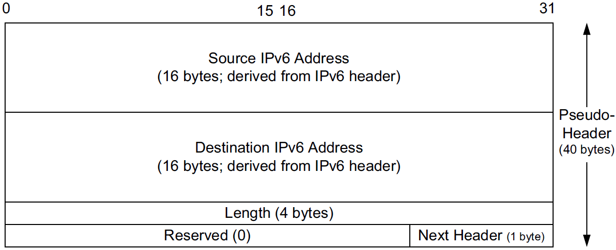
A related but more subtle distinction is that in IPv6, no IP-layer header checksum is present.
-
If UDP were to operate with checksums disabled, there would be no end-to-end check whatsoever on the correctness of the IP-layer addressing information.
-
When UDP is used with IPv6, a pseudo-header checksum, common to both UDP and TCP, is required.
-
In IPv6, the minimum MTU size is 1280 bytes (as opposed to the 576 bytes required by IPv4 as the minimum size required to be supported by all hosts).
-
IPv6 supports jumbograms (packets larger than 65,535 bytes).
When encapsulated in IPv6, a UDP/IPv6 datagram exceeding 65,535 bytes has its UDP Length field value set to 0.
x@node-0:~$ echo -n ' ' | nc -6u -w0 fe80::20c:29ff:fe85:2610%ens32 330root@node-0:~# tcpdump -tnv host fe80::20c:29ff:fe85:2610 and \( udp or icmp6 \) -X
tcpdump: listening on ens32, link-type EN10MB (Ethernet), snapshot length 262144 bytes
IP6 (flowlabel 0x6b6e1, hlim 64, next-header UDP (17) payload length: 9) fe80::20c:29ff:fe8c:df3f.33297 > fe80::20c:29ff:fe85:2610.330: [udp sum ok] UDP, length 1
0x0000: 6006 b6e1 0009 1140 fe80 0000 0000 0000 `......@........
0x0010: 020c 29ff fe8c df3f fe80 0000 0000 0000 ..)....?........
0x0020: 020c 29ff fe85 2610 8211 014a 0009 0506 ..)...&....J....
0x0030: 20
IP6 (flowlabel 0xa4c7d, hlim 64, next-header ICMPv6 (58) payload length: 57) fe80::20c:29ff:fe85:2610 > fe80::20c:29ff:fe8c:df3f: [icmp6 sum ok] ICMP6, destination unreachable, unreachable port, fe80::20c:29ff:fe85:2610 udp port 330
0x0000: 600a 4c7d 0039 3a40 fe80 0000 0000 0000 `.L}.9:@........
0x0010: 020c 29ff fe85 2610 fe80 0000 0000 0000 ..)...&.........
0x0020: 020c 29ff fe8c df3f 0104 7ef6 0000 0000 ..)....?..~.....
0x0030: 6006 b6e1 0009 1140 fe80 0000 0000 0000 `......@........
0x0040: 020c 29ff fe8c df3f fe80 0000 0000 0000 ..)....?........
0x0050: 020c 29ff fe85 2610 8211 014a 0009 0506 ..)...&....J....
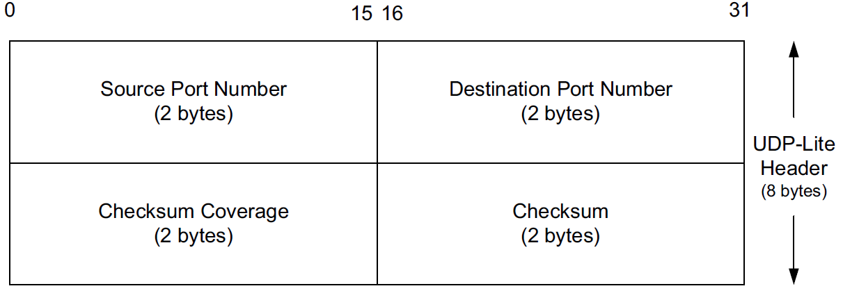
0x0060: 204. UDP-Lite
Some applications are tolerant of bit errors that may be introduced in the data they send and receive. Often, these types of applications wish to use UDP in order to avoid connection setup overhead or to use broadcast or multicast addressing, but UDP uses a checksum that covers either the entire payload or none of it (i.e., when no checksum is computed by the sender).
A protocol called UDP-Lite or UDPLite [RFC3828] addresses this issue by modifying the conventional UDP protocol to provide partial checksums. Such checksums cover only a portion of the payload in each UDP datagram.
UDP-Lite has its own IPv4 Protocol and IPv6 Next Header field value (136), so it effectively counts as a separate transport protocol.
5. IP Fragmentation
The link-layer framing normally imposes an upper limit on the maximum size of a frame that can be transmitted.
To keep the IP datagram abstraction consistent and isolated from link-layer details, IP employs fragmentation and reassembly.
-
Whenever the IP layer receives an IP datagram to send, it determines which local interface the datagram is to be sent over next (via a forwarding table lookup) and what MTU is required.
IP compares the outgoing interface’s MTU with the datagram size and performs fragmentation if the datagram is too large.
-
Fragmentation in IPv4 can take place at the original sending host and at any intermediate routers along the end-to-end path. Note that datagram fragments can themselves be fragmented.
-
Fragmentation in IPv6 is somewhat different because only the source is permitted to perform fragmentation.
-
When an IP datagram is fragmented, it is not reassembled until it reaches its final destination.
5.1. Example: UDP/IPv4 Fragmentation
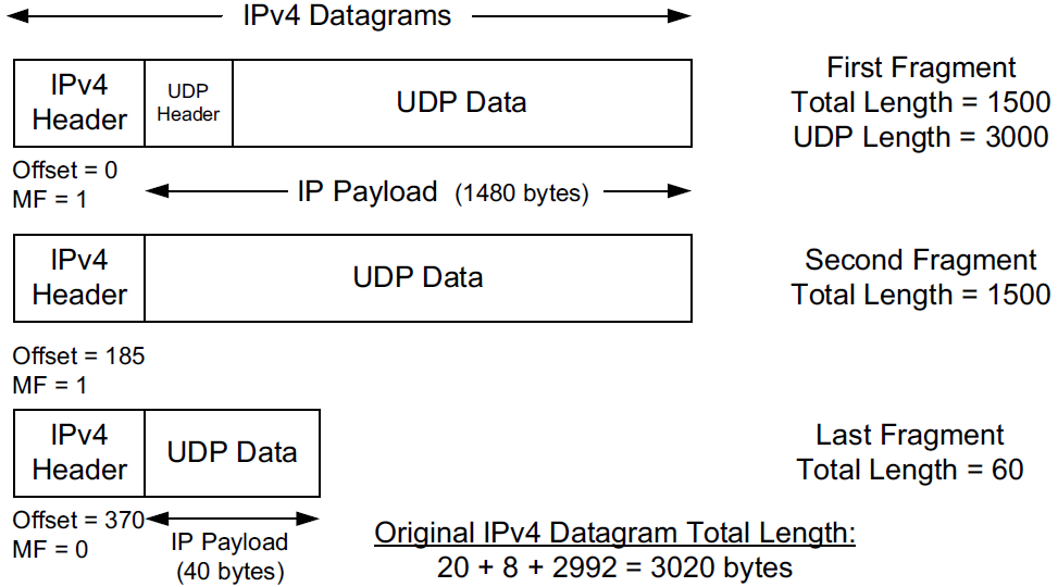
-
The original UDP datagram included 2992 bytes of application (UDP payload) data and 8 bytes of UDP header, resulting in an IPv4 Total Length field value of 3020 bytes (recall that this size includes a 20-byte IPv4 header as well).
When this datagram was fragmented into three packets, 40 extra bytes were created (20 bytes for each of the newly created IPv4 fragment headers). Thus, the total number of bytes sent is 3060, an increase in IP-layer overhead of about 1.3%.
-
The Identification field value (set by the original sender) is copied to each fragment and is used to group them together when they arrive.
-
The Fragment Offset field gives the offset of the first byte of the fragment payload byte in the original IPv4 datagram (in 8-byte units).
-
Finally, the MF bit field indicates whether more fragments in the datagram should be expected and is 0 only in the final fragment.
Because each Offset field is relative to the original datagram, the reassembly process can handle fragments that arrive out of order.
When a datagram is fragmented, the Total Length field in the IPv4 header of each fragment is changed to be the total size of that fragment.
x@node-0:$ ip addr show ens32
2: ens32: <BROADCAST,MULTICAST,UP,LOWER_UP> mtu 1500 qdisc pfifo_fast state UP group default qlen 1000
    link/ether 00:0c:29:8c:df:3f brd ff:ff:ff:ff:ff:ff
    altname enp2s0
    inet 192.168.91.128/24 brd 192.168.91.255 scope global ens32
       valid_lft forever preferred_lft forever

x@node-0:$ dd bs=2992 if=/dev/zero count=1 status=none | nc -w0 -u -s 192.168.91.128 192.168.91.137 330
root@node-0:~# tcpdump -tnvvv -i ens32 host 192.168.91.137 and udp
IP (tos 0x0, ttl 64, id 4494, offset 0, flags [+], proto UDP (17), length 1500)
192.168.91.128.45401 > 192.168.91.137.330: UDP, length 2992
IP (tos 0x0, ttl 64, id 4494, offset 1480, flags [+], proto UDP (17), length 1500)
192.168.91.128 > 192.168.91.137: ip-proto-17
IP (tos 0x0, ttl 64, id 4494, offset 2960, flags [none], proto UDP (17), length 60)
192.168.91.128 > 192.168.91.137: ip-proto-17Using UDP, it is easy to generate IP fragmentation. On an Ethernet,
-
the maximum amount of data in a frame is ordinarily 1500 bytes,
-
which leaves at most 1472 bytes for application data to avoid fragmentation, assuming 20 bytes for the IPv4 header and 8 bytes for the UDP header.
x@node-0:~$ ip addr show  ens32
2: ens32: <BROADCAST,MULTICAST,UP,LOWER_UP> mtu 1500 qdisc pfifo_fast state UP group default qlen 1000
    link/ether 00:0c:29:8c:df:3f brd ff:ff:ff:ff:ff:ff
    altname enp2s0
    inet 192.168.91.128/24 brd 192.168.91.255 scope global ens32
       valid_lft forever preferred_lft forever

x@node-0:~$ sudo nping -c 1 --udp -g 2022 --data-length 1473 --mtu 1600 --df -p 2019 192.168.91.137

Warning: fragmentation (mtu=1600) requested but the payload is too small already (1481)
sendto in send_ip_packet_sd: sendto(4, packet, 1501, 0, 192.168.91.137, 16) => Message too long
Offending packet: UDP 192.168.91.128:2022 > 192.168.91.137:2019 ttl=64 id=47461 iplen=1501
SENT (0.0286s) UDP 192.168.91.128:2022 > 192.168.91.137:2019 ttl=64 id=47461 iplen=1501
nping_event_handler(): READ-PCAP killed: Message too long

x@node-0:~$ sudo nping -c 1 --udp -g 2022 --data-length 1472 --mtu 1600 --df -p 2019 192.168.91.137

Warning: fragmentation (mtu=1600) requested but the payload is too small already (1480)
SENT (0.0275s) UDP 192.168.91.128:2022 > 192.168.91.137:2019 ttl=64 id=30623 iplen=1500
RCVD (0.0286s) ICMP [192.168.91.137 > 192.168.91.128 Port 2019 unreachable (type=3/code=3) ] IP [ttl=64 id=8055 iplen=576 ]

x@node-0:~$ sudo nping -c 1 --udp -g 2022 --data-length 1473 --mtu 1472 --df -p 2019 192.168.91.137

Starting Nping 0.7.80 ( https://nmap.org/nping ) at 2022-12-07 16:22 CST
SENT (0.0214s) UDP 192.168.91.128:2022 > 192.168.91.137:2019 ttl=64 id=29894 iplen=1501
RCVD (0.0218s) ICMP [192.168.91.137 > 192.168.91.128 Port 2019 unreachable (type=3/code=3) ] IP [ttl=64 id=8998 iplen=576 ]
root@node-0:~# tcpdump -ntv host 192.168.91.128 and udp IP (tos 0x0, ttl 64, id 30623, offset 0, flags [DF], proto UDP (17), length 1500) 192.168.91.128.2022 > 192.168.91.137.2019: UDP, length 1472 IP (tos 0x0, ttl 64, id 29894, offset 0, flags [+], proto UDP (17), length 1492) 192.168.91.128.2022 > 192.168.91.137.2019: UDP, length 1473 IP (tos 0x0, ttl 64, id 29894, offset 1472, flags [none], proto UDP (17), length 29) 192.168.91.128 > 192.168.91.137: ip-proto-17
If one fragment is lost, the entire datagram is lost.
-
There is no way to resend only one fragment of a datagram.
-
When a fragment of a TCP segment is lost, TCP retransmits the entire TCP segment, which corresponds to an entire IP datagram.
-
Some UDP-based applications perform timeout and retransmission themselves, but this happens at a layer above UDP.
Indeed, if the fragmentation was done by an intermediate router, and not the originating system, there is no way for the originating system to know how the datagram was fragmented.
For this reason, fragmentation is often avoided.
5.2. Reassembly Timeout
The IP layer must start a timer when any fragment of a datagram first arrives. If this were not done, fragments that never arrive could eventually cause the receiver to run out of buffers and can constitute a form of attack opportunity.
6. Path MTU Discovery with UDP
For a protocol such as UDP, in which the calling application is generally in control of the outgoing datagram size, it is useful if there is some way to determine an appropriate datagram size if fragmentation is to be avoided.
Conventional PMTUD uses ICMP PTB messages in determining the largest packet size along a routing path that can be used without inducing fragmentation. These messages are typically processed below the UDP layer and are not directly visible to an application, so
-
either an API call is used for the application to learn the best current estimate of the path MTU size for each destination with which it has communicated,
-
or the IP layer can perform PMTUD independently without the application knowing.
The IP layer often caches PMTUD information on a per-destination basis and times it out if it is not refreshed.
x@node-1:~$ sudo sysctl net.ipv4.ip_forward
net.ipv4.ip_forward = 1

x@node-1:~$ ip a show ens32
2: ens32: <BROADCAST,MULTICAST,UP,LOWER_UP> mtu 900 qdisc pfifo_fast state UP group default qlen 1000
    link/ether 00:0c:29:85:26:10 brd ff:ff:ff:ff:ff:ff
    inet 192.168.91.137/24 brd 192.168.91.255 scope global ens32
       valid_lft forever preferred_lft forever
x@node-0:~$ ip r
default via 192.168.91.137 dev ens32
192.168.91.0/24 dev ens32 proto kernel scope link src 192.168.91.128
x@node-0:~$ ping -M do -s 1472 -c 1 10.170.109.10
PING 10.170.109.10 (10.170.109.10) 1472(1500) bytes of data.
ping: local error: message too long, mtu=900
--- 10.170.109.10 ping statistics ---
1 packets transmitted, 0 received, +1 errors, 100% packet loss, time 0ms
x@node-0:~$ ip r show cache
10.170.109.10 via 192.168.91.137 dev ens32
cache expires 578sec mtu 900|
Path MTU discovery can sometimes cause problems because firewalls and filtering gateways may drop ICMP traffic indiscriminately, which can harm the PMTU discovery algorithm. Because of this, it is possible to disable PMTU discovery on a system-wide or finer-granularity basis.
An alternative to conventional PMTUD that does not use ICMP has also been developed [RFC4821]. |
7. Interaction between IP Fragmentation and ARP/ND
Using UDP, we can see the relationship between induced IP fragmentation and typical implementations of ARP.
Recall that ARP is used to map IP-layer addresses to corresponding MAC-layer addresses on the same IPv4 subnet.
The questions with which we are concerned include, When multiple fragments are to be sent, how many ARP messages should be generated, and how many of the fragments are held until a pending ARP request/response is completed? (Similar questions apply with IPv6 ND.)
Returning to our host and LAN using a 1500-byte MTU, we use the following two commands to see the answer:
x@node-0:~$ ping -s 8192 -c 1 192.168.91.110
PING 192.168.91.110 (192.168.91.110) 8192(8220) bytes of data.
From 192.168.91.128 icmp_seq=1 Destination Host Unreachable

--- 192.168.91.110 ping statistics ---
1 packets transmitted, 0 received, +1 errors, 100% packet loss, time 0ms

x@node-0:~$ ping -s 8192 -c 1 192.168.91.137
PING 192.168.91.137 (192.168.91.137) 8192(8220) bytes of data.
8200 bytes from 192.168.91.137: icmp_seq=1 ttl=64 time=1.13 ms

--- 192.168.91.137 ping statistics ---
1 packets transmitted, 1 received, 0% packet loss, time 0ms
rtt min/avg/max/mdev = 1.129/1.129/1.129/0.000 ms
x@node-0:~$ sudo tcpdump -i ens32 -tttnv icmp or arp
tcpdump: listening on ens32, link-type EN10MB (Ethernet), snapshot length 262144 bytes
00:00:00.000000 ARP, Ethernet (len 6), IPv4 (len 4), Request who-has 192.168.91.110 tell 192.168.91.128, length 28
00:00:01.030208 ARP, Ethernet (len 6), IPv4 (len 4), Request who-has 192.168.91.110 tell 192.168.91.128, length 28
00:00:01.024150 ARP, Ethernet (len 6), IPv4 (len 4), Request who-has 192.168.91.110 tell 192.168.91.128, length 28
00:00:06.177783 ARP, Ethernet (len 6), IPv4 (len 4), Request who-has 192.168.91.137 tell 192.168.91.128, length 28
00:00:00.000262 ARP, Ethernet (len 6), IPv4 (len 4), Reply 192.168.91.137 is-at 00:0c:29:85:26:10, length 46
00:00:00.000009 IP (tos 0x0, ttl 64, id 21330, offset 0, flags [+], proto ICMP (1), length 1500)
192.168.91.128 > 192.168.91.137: ICMP echo request, id 2725, seq 1, length 1480
00:00:00.000030 IP (tos 0x0, ttl 64, id 21330, offset 1480, flags [+], proto ICMP (1), length 1500)
192.168.91.128 > 192.168.91.137: ip-proto-1
00:00:00.000022 IP (tos 0x0, ttl 64, id 21330, offset 2960, flags [+], proto ICMP (1), length 1500)
192.168.91.128 > 192.168.91.137: ip-proto-1
00:00:00.000022 IP (tos 0x0, ttl 64, id 21330, offset 4440, flags [+], proto ICMP (1), length 1500)
192.168.91.128 > 192.168.91.137: ip-proto-1
00:00:00.000023 IP (tos 0x0, ttl 64, id 21330, offset 5920, flags [+], proto ICMP (1), length 1500)
192.168.91.128 > 192.168.91.137: ip-proto-1
00:00:00.000019 IP (tos 0x0, ttl 64, id 21330, offset 7400, flags [none], proto ICMP (1), length 820)
192.168.91.128 > 192.168.91.137: ip-proto-1
...8. Maximum UDP Datagram Size
Theoretically, the maximum size of an IPv4 datagram is 65,535 bytes, imposed by the 16-bit Total Length field in the IPv4 header. With an optionless IPv4 header of 20 bytes and a UDP header of 8 bytes, this leaves a maximum of 65,507 bytes of user data in a UDP datagram.
For IPv6, the 16-bit Payload Length field permits an effective UDP payload of 65,527 bytes (8 of the 65,535 IPv6 payload bytes are used for the UDP header), assuming jumbograms are not being used.
There are two main reasons why a full-size datagram of these sizes may not be delivered end-to-end, however.
-
First, the system’s local protocol implementation may have some limitation.
-
Second, the receiving application may not be prepared to handle such large datagrams.
8.1. Implementation Limitations
Protocol implementations provide an API to applications that pick some default buffer size for sending and receiving.
-
Some implementations provide defaults that are less than the maximum IP datagram size,
-
and some actually do not support sending datagrams larger than a few tens of kilobytes (although this problem is not common).
The sockets API provides a set of functions that an application can call to set or query the size of the receive and send buffers.
-
For a UDP socket, this size is directly related to the maximum size of UDP datagram the application can read or write.
-
Typical default values are 8192 bytes or 65,535 bytes, but these can generally be made larger by invoking the
setsockopt()API call.
Many UDP applications (e.g. DNS, DHCP, etc.) are designed to restrict their application data size to 512 bytes or less (resulting in IPv4 datagrams under 576 bytes), to stay below this limit.
Total Length:  16 bits

    Total Length is the length of the datagram, measured in octets,
    including internet header and data.  This field allows the length of
    a datagram to be up to 65,535 octets.  Such long datagrams are
    impractical for most hosts and networks.  All hosts must be prepared
    to accept datagrams of up to 576 octets (whether they arrive whole
    or in fragments).  It is recommended that hosts only send datagrams
    larger than 576 octets if they have assurance that the destination
    is prepared to accept the larger datagrams.

    The number 576 is selected to allow a reasonable sized data block to
    be transmitted in addition to the required header information.  For
    example, this size allows a data block of 512 octets plus 64 header
    octets to fit in a datagram.  The maximal internet header is 60
    octets, and a typical internet header is 20 octets, allowing a
    margin for headers of higher level protocols.
8.2. Datagram Truncation
Just because UDP/IP is capable of sending and receiving a datagram of a given (large) size does not mean the receiving application is prepared to read that size.
UDP programming interfaces allow the application to specify the maximum number of bytes to return each time a network read operation completes.
What happens if the received datagram exceeds the size specified?
-
In most cases, the answer to this question is that the API truncates the datagram, discarding any excess data in the datagram beyond the number of bytes specified by the receiving application.
-
However, the exact behavior varies from implementation to implementation.
Some systems provide the unconsumed portion of the datagram in subsequent read operations,
and others inform the caller of how much data was truncated (or, in yet other cases, that some data was truncated, but not exactly how much).
In Linux, the MSG_TRUNC option may be given to the sockets API to discover how much data was truncated.
|
9. UDP Server Design
There are some characteristics of UDP that affect the design and implementation of networking application software wishing to use it [RFC5405].
Servers typically interact with the operating system, and most need a way to handle multiple clients at the same time.
In the typical client/server scenario, a client starts, immediately communicates with a single server, and is done. Servers, on the other hand, start and then go to sleep, waiting for a client’s request to arrive. They awaken when a client’s datagram arrives, which usually requires the server to evaluate the request and possibly perform further processing.
9.1. IP Addresses and UDP Port Numbers
What arrives at a UDP server from a client is a UDP datagram.
-
The IP header contains the source and destination IP addresses,
-
and the UDP header contains the source and destination UDP port numbers.
-
When an application receives a UDP message,
-
the IP and UDP headers have been stripped off;
-
the application must be told by the operating system in some other way who sent the message (the source IP address and port number), if it intends to furnish a reply. This feature allows a UDP server to handle multiple clients.
-
Some servers need to know to whom the datagram was sent, that is, the destination IP address.
-
Any server wishing to perform its tasks differently depending on the destination IP address selected by the client would require access to the destination IP address information.
-
In addition, some services may respond differently if the destination address is broadcast or multicast.
| A DNS server is one type of server that is sensitive to the destination IP address. It can use this information to arrange a particular sorting order on the address mappings it returns. |
9.2. Restricting Local IP Addresses
Most UDP servers wildcard their local IP address when they bind a UDP endpoint. This means that an incoming UDP datagram destined for the server’s port is accepted on any local IP address (any IP address in use on the local machine, including the local loopback address).
x@node-0:~$ ncat -vlu 7777
Ncat: Version 7.80 ( https://nmap.org/ncat )
Ncat: Listening on :::7777
Ncat: Listening on 0.0.0.0:7777
x@node-0:~$ netstat -lun
Active Internet connections (only servers)
Proto Recv-Q Send-Q Local Address Foreign Address State
udp 0 0 0.0.0.0:7777 0.0.0.0:*
udp6 0 0 :::7777 :::*When the server creates its endpoint, it can specify one of the host’s local IP addresses, including a broadcast address, as the local IP address for the endpoint. In such cases, incoming UDP datagrams are then passed to this endpoint only if the destination IP address matches the specified local address.
x@node-0:~$ ncat -vlu 127.0.0.1 7777
Ncat: Version 7.80 ( https://nmap.org/ncat )
Ncat: Listening on 127.0.0.1:7777
x@node-0:~$ netstat -lun
Active Internet connections (only servers)
Proto Recv-Q Send-Q Local Address Foreign Address State
udp 0 0 127.0.0.1:7777 0.0.0.0:*x@node-0:~$ nping -c 1 --udp -p 7777 192.168.91.128
SENT (0.0026s) UDP packet with 4 bytes to 192.168.91.128:7777
ERR: (0.0026s) READ to 192.168.91.128:7777 failed: Connection refusedx@node-0:~$ sudo tcpdump -tnv udp or icmp -i any
lo In IP (tos 0x0, ttl 64, id 23511, offset 0, flags [DF], proto UDP (17), length 32)
192.168.91.128.49849 > 192.168.91.128.7777: UDP, length 4
lo In IP (tos 0xc0, ttl 64, id 60067, offset 0, flags [none], proto ICMP (1), length 60)
192.168.91.128 > 192.168.91.128: ICMP 192.168.91.128 udp port 7777 unreachable, length 40
IP (tos 0x0, ttl 64, id 23511, offset 0, flags [DF], proto UDP (17), length 32)
192.168.91.128.49849 > 192.168.91.128.7777: UDP, length 49.3. Using Multiple Addresses
It is possible to start different servers on the same port number, each with a different local IP address.
x@node-0:~$ ip a show ens32
2: ens32: <BROADCAST,MULTICAST,UP,LOWER_UP> mtu 1500 qdisc pfifo_fast state UP group default qlen 1000
    link/ether 00:0c:29:8c:df:3f brd ff:ff:ff:ff:ff:ff
    altname enp2s0
    inet 192.168.91.128/24 brd 192.168.91.255 scope global ens32
       valid_lft forever preferred_lft forever
    inet 192.168.91.129/24 brd 192.168.91.255 scope global secondary ens32
       valid_lft forever preferred_lft forever
    inet 192.168.91.134/24 brd 192.168.91.255 scope global secondary dynamic ens32
       valid_lft 1543sec preferred_lft 1543sec
    inet6 fe80::20c:29ff:fe8c:df3f/64 scope link
       valid_lft forever preferred_lft forever

x@node-0:~$ ncat -lu 8888
x@node-0:~$ ncat -lu 192.168.91.129 8888
x@node-0:~$ ncat -lu 192.168.91.128 8888
x@node-0:~$ netstat -nlu
Active Internet connections (only servers)
Proto Recv-Q Send-Q Local Address Foreign Address State
udp 0 0 192.168.91.129:8888 0.0.0.0:*
udp 0 0 192.168.91.128:8888 0.0.0.0:*
udp 0 0 0.0.0.0:8888 0.0.0.0:*
udp6 0 0 :::8888 :::*There is a priority implied when an endpoint with a wildcard address exists.
-
An endpoint with a specific IP address that matches the destination IP address is always chosen over a wildcard.
-
The wildcard endpoint is used only when a specific match is not found.
9.4. Restricting Foreign IP Address
In all the netstat output that we showed earlier, the foreign IP address (i.e., the one not local to the host where the server is running) and foreign port number are shown as 0.0.0.0:*, meaning that the endpoint will accept an incoming UDP datagram from any IPv4 address and any port number.
However, there is an option to restrict the foreign address. This means that the endpoint receives UDP datagrams only from that specific IPv4 address and port number.
| Local Address | Foreign Address | Description |
|---|---|---|
local_IP.local_port |
foreign_IP.foreign_port |
Restricted to one client |
local_IP.local_port |
*.* (wildcard) |
Restricted to one local IP address and port (but for any client) |
*.local_port |
*.* (wildcard) |
Restricted to local port only |
9.5. Using Multiple Servers per Port
Although it is not specified in the RFCs, by default most implementations allow only one application endpoint at a time to be associated with any one (local IP address, UDP port number) pair for a given address family (i.e., IPv4 or IPv6).
When a UDP datagram arrives at a host destined for its IP address and an active port number, one copy is delivered to that single endpoint (e.g., a listening application).
The IP address of the endpoint can be the wildcard, as shown earlier, but only a single application can receive datagrams for the address(es) specified.
If we then try to start another server with the same wildcarded local address and the same port using the same address family, it does not work:
x@node-0:~$ socat - udp-listen:8888 & socat - udp-listen:8888
[1] 38249
2022/12/08 16:57:19 socat[38250] E bind(5, {AF=2 0.0.0.0:8888}, 16): Address already in use
In support of multicasting, multiple endpoints can be allowed to use the same (local IP address, UDP port number) pair, although the application normally must tell the API (i.e., specifing the SO_REUSEADDR option).
x@node-0:~$ socat - udp-listen:8888,reuseaddr & socat - udp-listen:8888,reuseaddr
[2] 38270
When a UDP datagram arrives whose destination IP address is a broadcast or multicast address, and there are multiple endpoints at the destination IP address and port number, one copy of the incoming datagram is passed to each endpoint.
-
The endpoint’s local IP address can be the wildcard, which matches any destination IP address.
x@node-0:~$ ncat -vlu4 192.168.91.255 9999
Ncat: Version 7.80 ( https://nmap.org/ncat )
Ncat: Listening on 192.168.91.255:9999
Ncat: Connection from 192.168.91.137.
hello
hello
x@node-0:~$ ncat -vlu4 9999 Ncat: Version 7.80 ( https://nmap.org/ncat ) Ncat: Listening on 0.0.0.0:9999 Ncat: Connection from 192.168.91.137. hello hellox@node-0:~$ netstat -nlu4 Active Internet connections (only servers) Proto Recv-Q Send-Q Local Address Foreign Address State udp 0 0 192.168.91.255:9999 0.0.0.0:* udp 0 0 0.0.0.0:9999 0.0.0.0:*x@node-1:~$ echo 'hello' | nc -u 192.168.91.255 9999
But if a UDP datagram arrives whose destination IP address is a unicast address (i.e., an ordinary address), only a single copy of the datagram is delivered to one of the endpoints.
9.6. Spanning Address Families: IPv4 and IPv6
It is possible to write servers that span not only protocols (such as servers that respond to both TCP and UDP) but also across address families. That is, we may write a UDP server that responds to incoming requests for IPv4 as well as for IPv6.
While this may seem entirely straightforward (IPv6 addresses are just additional IP addresses on the same host that happen to be 128 bits long), there is a subtlety related to the sharing of the port space.
On some systems, the port space between IPv6 and IPv4 for UDP (and TCP) is shared. This means that if a service binds to a UDP port using IPv4, it is also allocated the same port in the IPv6 port space (and vice versa), preventing other services from using it (unless the SO_REUSEADDR socket option is used).
Furthermore, because IPv6 addresses can encode IPv4 addresses in an interoperable way, wildcard bindings in IPv6 may receive incoming IPv4 traffic.
9.7. Lack of Flow and Congestion Control
Most UDP servers are iterative servers.
-
This means that a single server thread (or process) handles all the client requests on a single UDP port (e.g., the server’s well-known port).
-
Normally there is a limited-size input queue associated with each UDP port that an application is using.
This means that requests arriving at about the same time from different clients are automatically queued by UDP.
-
The received UDP datagrams are passed to the application (when it asks for the next one) in the order in which they were received (i.e., FCFS—first come, first served).
It is possible, however, for this queue to overflow, causing the UDP implementation to discard incoming datagrams.
-
This can happen even if only one client is being served because UDP provides no flow control (that is, no way for the server to tell the client to slow down).
-
Because UDP is a connectionless protocol with no reliability mechanism of its own, applications are not told when the UDP input queue overflows. The excess datagrams are just discarded by UDP.
Another concern arises from the fact that queues are also present in the IP routers between the sender and the receiver—in the middle of the network.
-
When these queues become full, traffic may be discarded in a fashion similar to that of the UDP input queue.
-
When this happens, the network is said to be congested.
Congestion is undesirable because it affects all network users with traffic that traverses the point where congestion is occurring, as opposed to the UDP case previously, where only a single application server was affected.
UDP poses a special concern for congestion because it has no way of being informed that it should slow down its sending rate if the network is being driven into congestion. It also has no mechanism for slowing down, even if it were told to do so. Thus, it is said to lack congestion control.
Congestion control is a complex subject and still an active area of research.